
The first revision of this project was shipped in November of 2020, but the subsequent redesign was commissioned and completed the following summer in 2021. This post primarily a journey through that second revision, and it’s publication comes some time after the deliverable was shipped to the client.
Engineering requirements that arrive downstream from artistic intent are my favorite constraints to work inside of. It forces the engineer to assume the role of the artist, considering the feelings and ideas that will be communicated to the audience with the piece. The engineer also has to become an audience member to understand other factors about how viewing will take place, if the environment will change such that the piece needs to respond in kind. The space in between these to roles needs to be projected into the standard space of product requirements, weights, tolerances, latencies etc. that are common in the profession.
As a part of my freelance practice, interdisciplinary artist Sara Dittrich and I recently collaborated on a series of projects, adding to our shared body of work. The most technically challenging part of these most recent works was a component of her piece called The Tender Interval. I urge you to go read her documentation on this project, there is a great video overview as well.
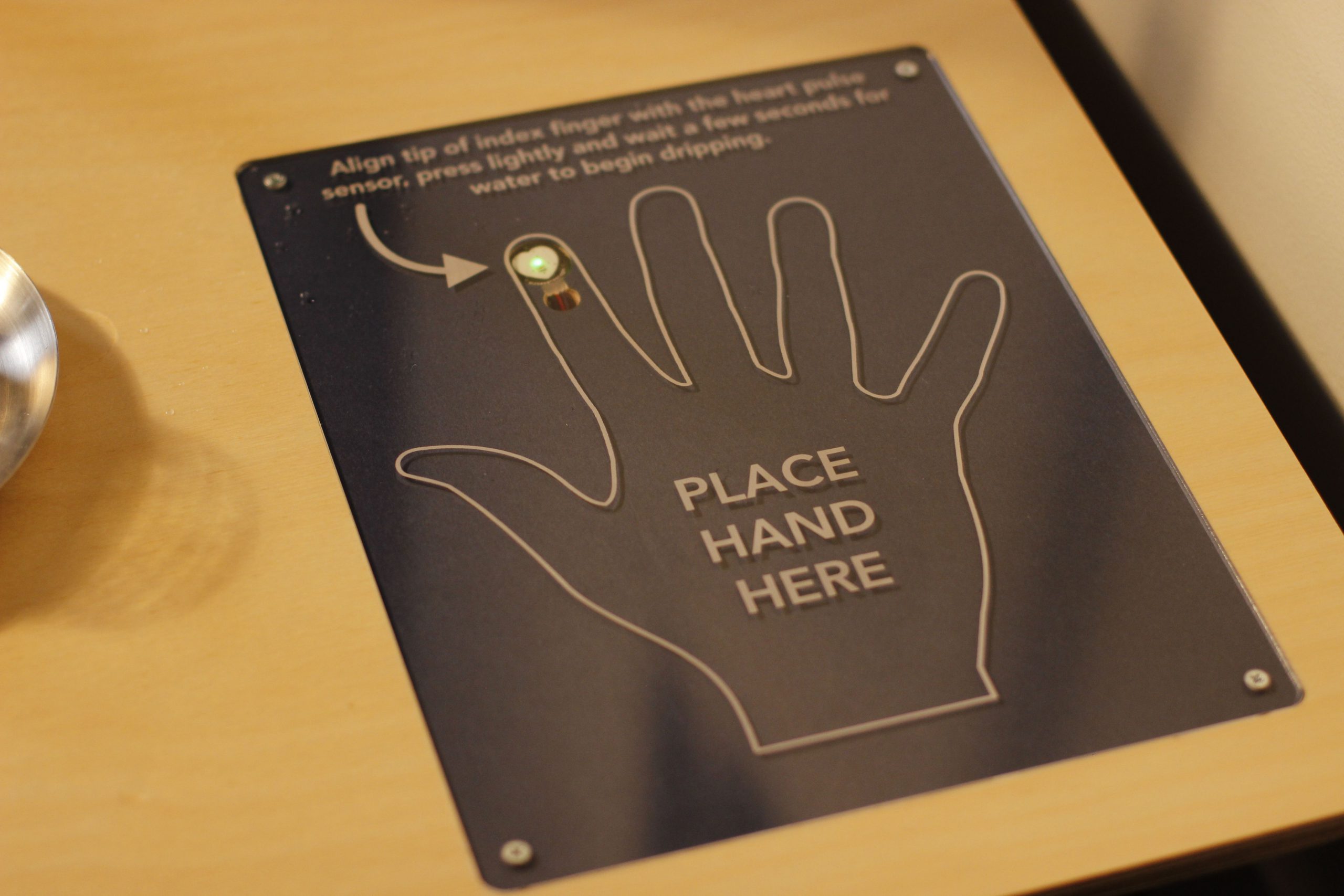
Two performers sit at a table across from each other, above them is an IV stand with two containers full of water. Embedded in the table are two fingerprint sensors, one for each of the people seated at the table. Performers place their hands on the table, with their index fingers covering the sensors. Each time their heart beats, their container emits a single drop of water, which falls from above them into a glass placed next to them on the table. Once their glass fills, they drink the water. Optionally, virtual viewers on twitch can take the place of the second performer by sending commands on twitch that deposit water droplets into the second glass.
The device responsible for creating the water droplets (the dripper) ended up being a very technically demanding object to create. The preeminent cause of this difficulty was the requirement that it operate in complete silence. Since the first showings of this piece were done virtually due to the pandemic, we were able to punt this problem and get the around noisy operating levels of V1 using strategic microphone placement. However, this piece would eventually be shown in a gallery setting, which would require totally silent operation.
The following is a feature overview and demonstration of the completed silent dripper:
If you’re interested in building one of these to add to your own projects, there is a github organization that contains the:
- Arduino firmware to read heartbeats and control the motor drivers.
- KiCAD projects for the circuit schematic, PCB layout and the connector PCB.
- Mechanical CAD exports for the printed parts.
Per usual, please send along photos of rebuilds of this project. Submit PRs if you have improvements, or open issues if your run into problems along the way.
The rest of this post will be a deep dive into earlier iterations of this project, and an closer look at the design details and challenges of the final design. It’s easier to understand why a second iteration was needed after reviewing the shortcomings of version 1, so that’s where we’ll start.
Version 1


The design is centered around a 12V DC peristaltic pump, the intllab DP-DIY 12V model. Peristaltic pumps are the tool to reach for when food safety is a requirement. The liquid that is getting pumped never passes over any of the mechanisms used to actually pump the liquid, it stays inside the tubing. They’re also very accurate in small amounts. You see these things used all over the place in DIY projects. Irrigation systems, low pressure vacuums etc. They’re always a part of bartender robots.


The pump is mounted in a 3D printed housing, and there is a bit of plumbing to be able to use standard hosing barbs to form the drops. This is an extremely conservative approach. Having never worked with water and printed parts I was concerned with the idea of leaks between layers or material breakdown over time. The plumbing takes up a lot of space, almost as much space as the pump.
The power connector is a standard barrel jack, and there are no other electronics inside the housing.


After some tuning, it became possible to get drops forming reliably with this design, and it was very easy to drive the motors using an nMOS driven via PWM.
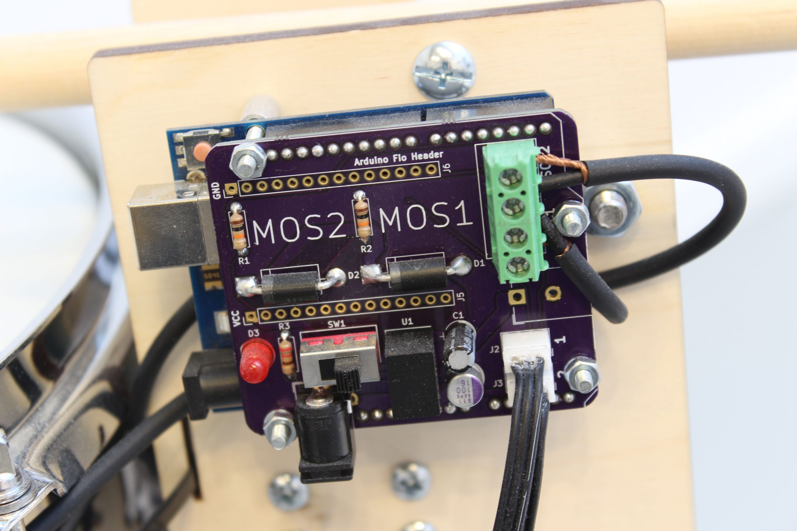
Being able to use an nMOS circuit to drive the pumps was an engineering requirement, because as a part of a previous job with this client I had designed a PCB and written firmware with a very similar purpose. Instead of water droplets, heartbeats would energize a solenoid attached to a drum stick that would strike a snare or bass drum.


To save time, we wanted to re-use the PCB and Arduino firmware for the dripper project. I ended up paying big for this shortcut, but more on that later. That installation was called Cadence, and the PCB was is called the cadence PCB.
With direct-drive PWM comes PWM coil whine, one of the direct contributors to the acoustic created by the dripper. The motor created a high-pitched whine while being driven by a PWM signal directly. You’re probably familiar with this sound if you’ve used an RC car or drone.
The other main contributor of acoustic noise was the squeaking of the pump’s peristaltic mechanism. As an aside, the mechanical component of this pump is phenomenal. There are no gears, no d-shaft, no screws, nothing! The rollers are pinched in place with the elastic force from the tubing, and then the friction force between the motor’s axle and the rollers causes everything to rotate. This minimalist design means you can’t use lubricants to try and reduce the friction and consequently the noise created by the pump. Introducing a lubricant causes the motor’s shaft to slip against the rollers, which causes the pump to size up.
These two sources of noise, the whine from the motor and the squeaking of the pump resulted in an unfortunately loud operating sound level. Drop production was reliable, but too loud for a gallery, the target setting of the next showing of this piece.
Noise aside, the design was globally inelegant. The tubing, bent 90 degrees without a guide, would sometimes kink. The manufacturing was overly complicated and consumed a considerable amount of time per dripper.
Again, these issues were totally fine for the twitch performances because of how controlled the environment was. I knew that the likelihood of a dripper breaking down was non-zero so I ended up shipping five of them even though only two were needed for the performances.
The Silent Dripper
A month of twitch performances behind us, it was time to settle back into the the dripper design. With silence as the main requirement, but with stability and manufacturability top of mind as well, I began a research phase.
If it wasn’t obvious, 3D printing is a favorite technology for prototyping and small volume production runs like this. Acoustic noise is also a concern when using 3D printers. You’ve probably seen people on hackaday modify their printers using Trinamic silentstepstick drivers to achieve a quieter working environment.
These drivers absolutely do what it says on the box, there’s no comparison between these parts and traditional drivers where sound is concerned. In my testing I found that they can’t output as much torque as say an A3967, but most of the time, especially in my application, they’re strong enough and the tradeoff is well worth it.
The prospect of being able to use these drivers to completely eliminate coil whine on the second second iteration was extremely promising. Being able to take advantage of this silent operation would require a pump fitted with a stepper motor rather than a DC motor. Luckily, dozens of these types of pumps exist and are even available for delivery with amazon prime! I ordered five different stepper pumps, and two more types of DC pumps to compare and make sure no stone went unturned.


Pumps produced by industrial suppliers that come with loudness specifications do exist but are often very large and very expensive. I also found that those pumps where mostly DC-style motors, and wouldn’t be compatible with the trinamic drivers. This is to say that while the following pumps are adequate the low-stress job of producing droplets of room-temperature water, tread lightly, and do your won evaluation for your specific application if extending this work.
Pump comparison introduction
The pump decision would prove to be the most critical decision in the entire design. After all, the dripper is just a housing for a pump.
Pumps were evaluated based on a few factors. Each pump was disassembled to understand how they operated, and to see if it would be possible to decrease their operating noise level. Put simply, the goal here is to find a quiet and small pump to build into the next iteration of the design.
MOUNTAIN ARK 4320792838 (DC Motor)


Product page: here.
Description: A small, black, submersible, centrifugal pump. There are small barb fittings on the inputs and outputs, but the pump can’t self-prime so it’s assumed this is going to be submerged in a reservoir.
Sound: Of all the pumps reviewed, this one is the clear winner in terms of the ratio between the amount of water flow to the operating noise level. It moves a ton of water and produces almost no noise. The problem is that getting it to reliably produce only single droplets of water as almost impossible. It would be great for a water feature in a garden but horrible for this application.
bayite BYT-7A006 (DC Motor)


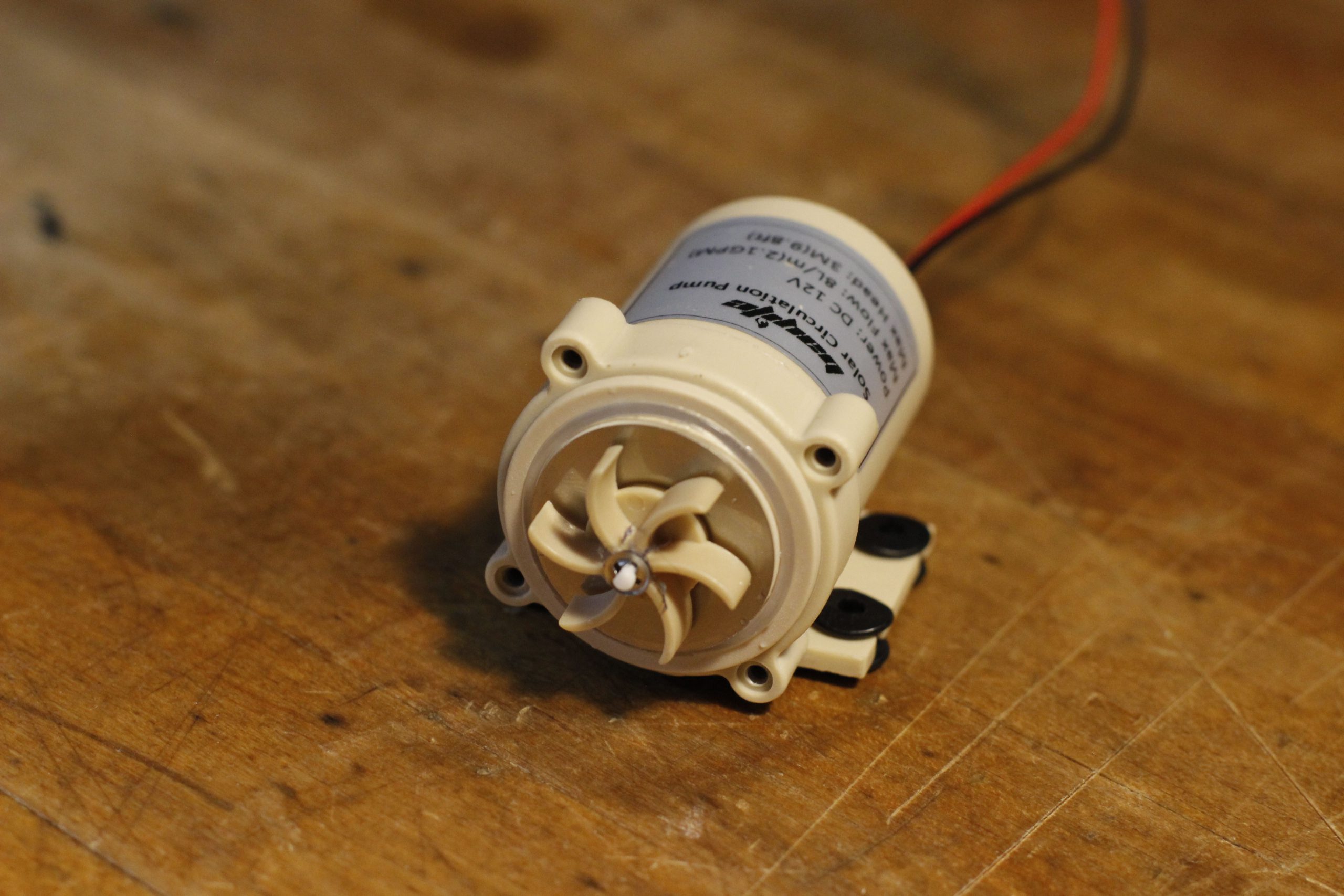
Product page: here.
Description: A medium sized, tan, submersible, centrifugal pump. Can move a lot of water, but makes distinct noise while operating. Again, wasn’t really suitable for the application, also couldn’t move small amounts of water to form drips.
Sound:: Makes a distinct whining noise while operating. There was also noise created by air bubbles rushing through the tube.
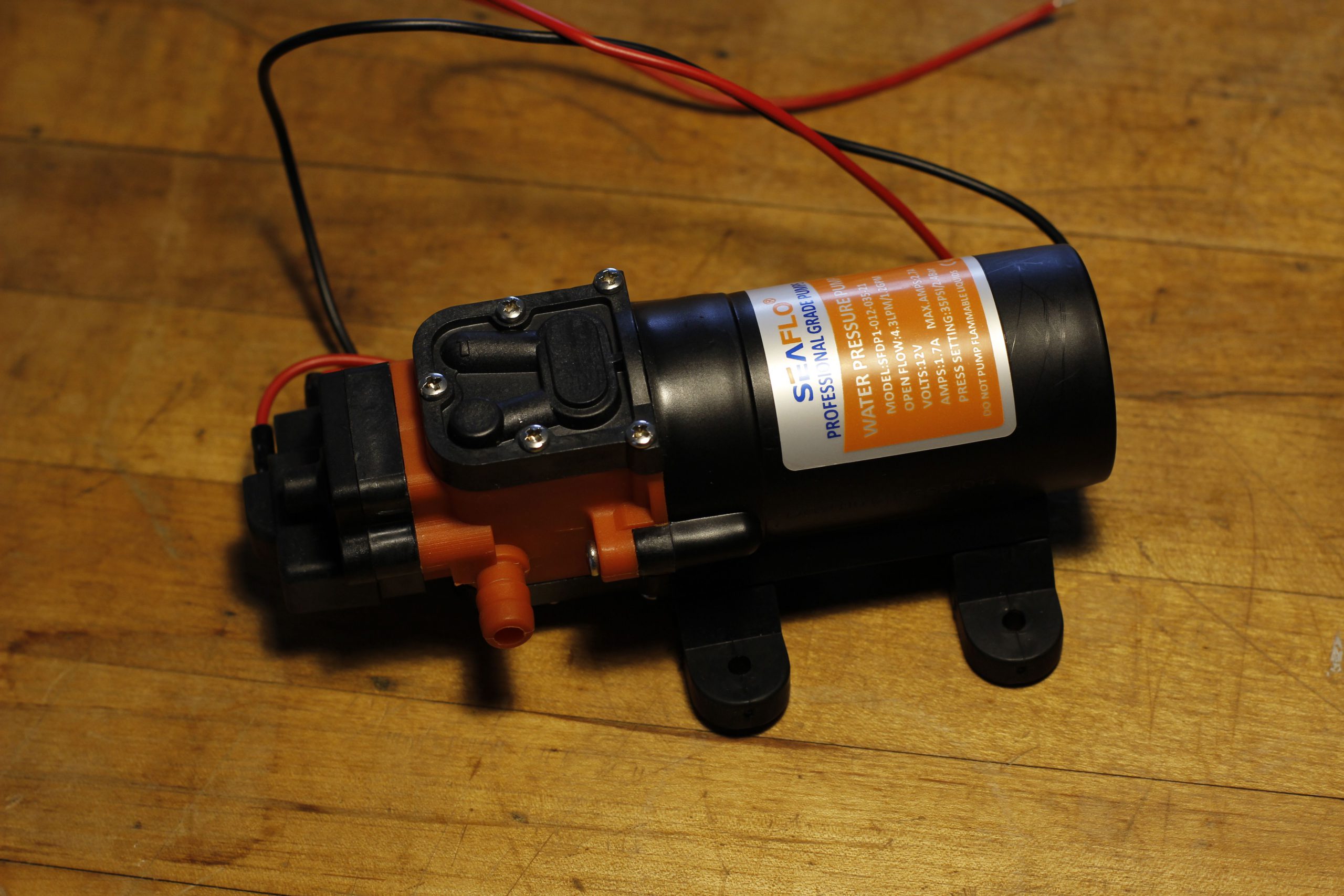
Seaflo SFDP1-012-035-21 (DC Motor)
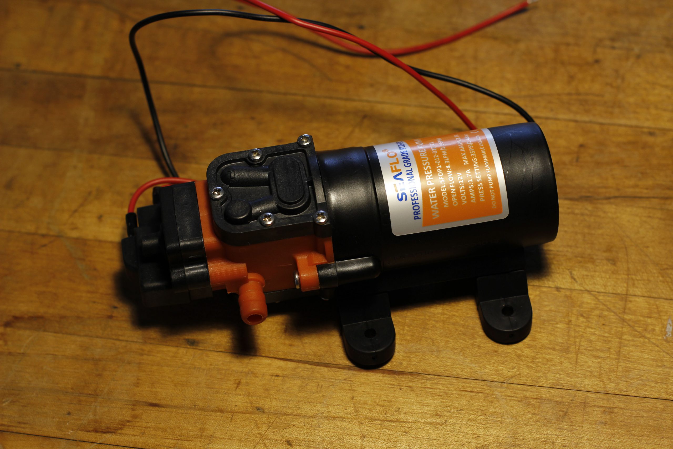
Product page: here.
Description: A large, diaphragm pump recycled from a previous project. It’s massive, and would be best suited for an outdoor shower build. I figured that it couldn’t hurt to compare it to the other pumps, drip forming ended up being possible which wasn’t viable on the centrifugal pumps.
Sound:: Loudest of the DC pumps, makes a droning/vibrating noise as the diaphragm operates.
Yanmis 1KUCIZ6Q8G (Stepper Motor)


Product page: here.
Description: A medium-sized, stepper motor peristaltic pump that didn’t work! I really liked the snapping mechanism to keep the tube tension, but this pump straight up did not move any liquid. I suspect that the tubing installed was too small.
It’s a shame, because this one checked a lot of boxes. The rollers are attached to the axle with a set screw, and the roller assembly is mostly metal with six roller contacts inside the housing.
Sound: Even though the pump couldn’t move any liquid, the motor still spun. While it did it was pretty quiet, you could hear the popping of the tube as air bubbles formed.
Yanmis KOF2BNRQDM (Stepper Motor)

Product page: here.
Description: A medium-sized, stepper motor peristaltic pump, the first pump I tried applying the white lithium grease to. This pump’s rollers had a very nice rubber coating, and were held in place with screws. Lots of metal in the internal pump mechanism as well.
Sound: This pump had a very quiet operating noise level. Very little rattling to be heard. Once the lubricant was added this pump was completely silent. This proved the concept that the goal of silent operating was possible, a welcomed revelation.
INTLLAB DP-520-48S (Stepper Motor)


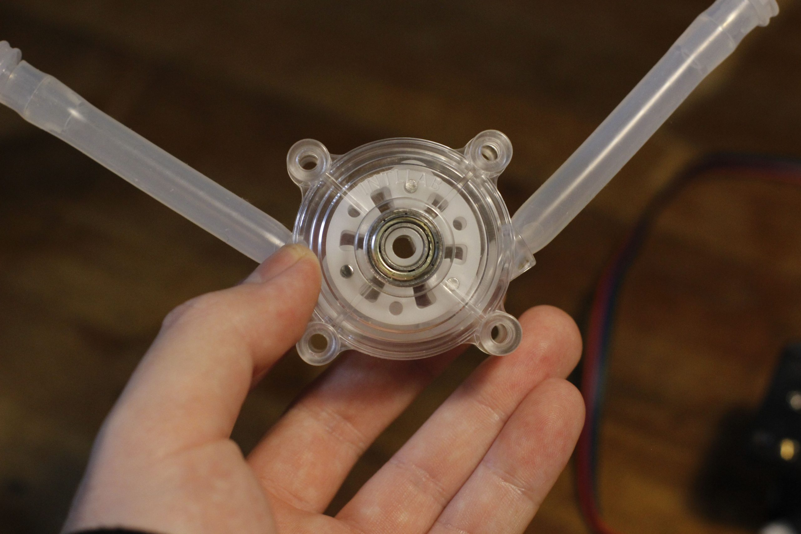


Product page: here.
Description: A medium-sized, stepper motor peristaltic pump. This pump has a very similar construction to the Yanmis KOF2BNRQDM. However, the tubing extends horizontally through the pump instead of a 180 degree turn. Unlike the Yanmis KOF2BNRQDM, the roller mechanism is mostly made of plastic, which impacted noise levels. The assembled pumping mechanism can be completely separated from the motor which is interesting. The motors axle mates into the all plastic roller without a set screw, but there is a d-shaft. There’s a bearing where the roller mechanism contacts the outside of the pumping mechanism. Slightly bigger than the Yanmis KOF2BNRQDM.
Sound: During operation this pump is pretty loud, there is plastic squeaking noises and clicking.
MaschinenReich XP1500 (Stepper Motor)


Product page: here.
Description: A large, stepper motor inline peristaltic pump. I saw a range of pumps like this online, where the tubing is inline with the pumping mechanism. The point is to be able to quickly change out the tubing without having to disassemble the entire pump. This pump is massive and could probably move a ton of water. The point here is to evaluate how well this topology would perform in general, because obviously this particular model is too large.
Sound: Before even powering the pump on it was obvious that it was unsuitable for this application due to it’s size. However, the sound level is impressive, it was about as loud as the other stepper pumps while being nearly twice as large.
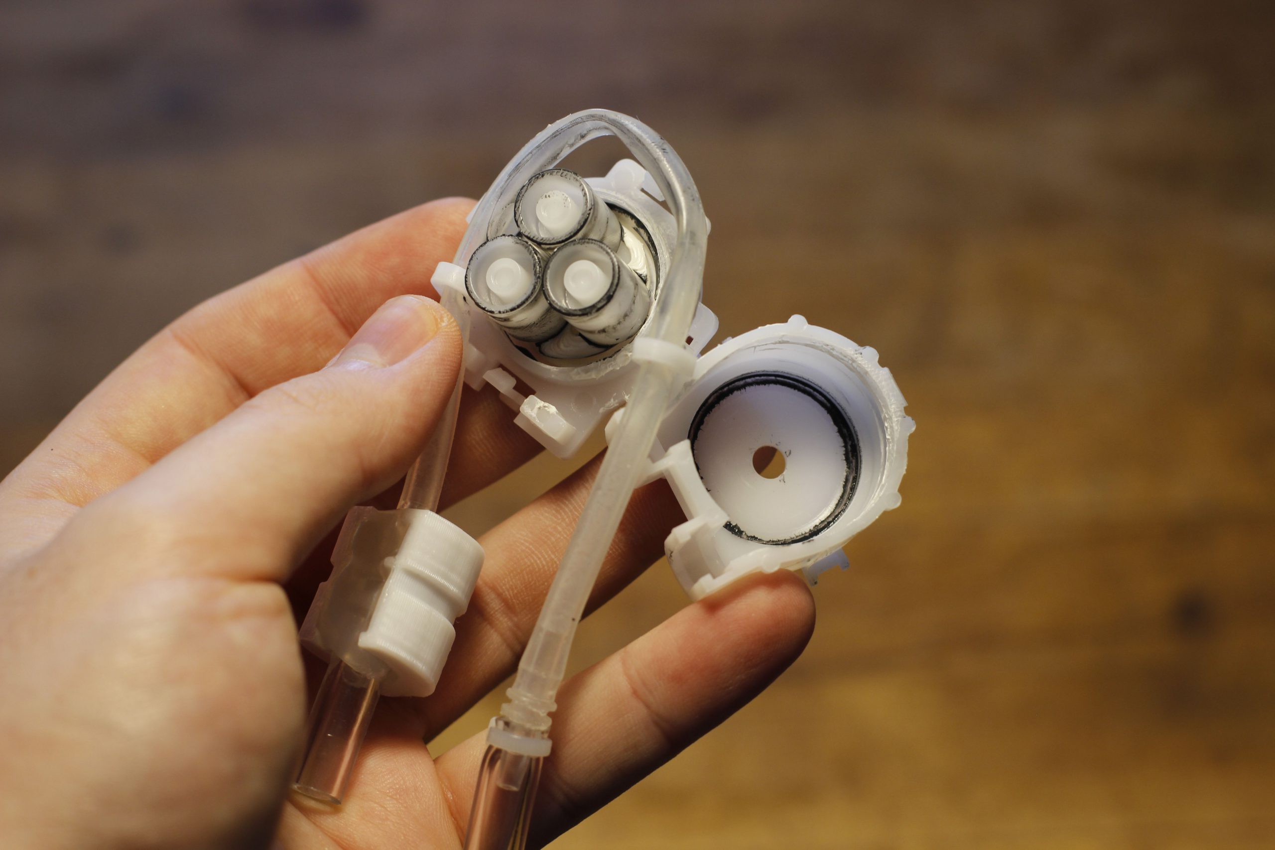
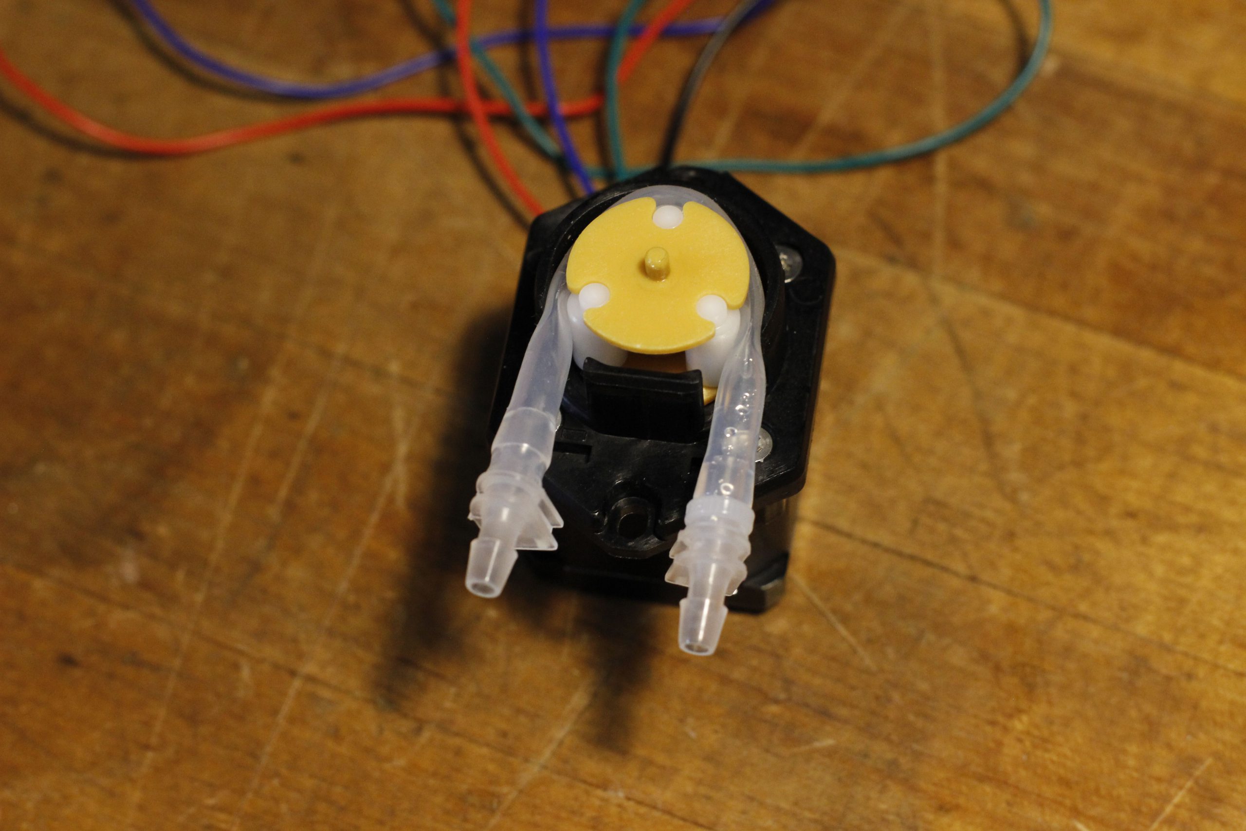
Winning Pump – MaschinenReich XP88 ST01 (Stepper Motor)


Product page: here.
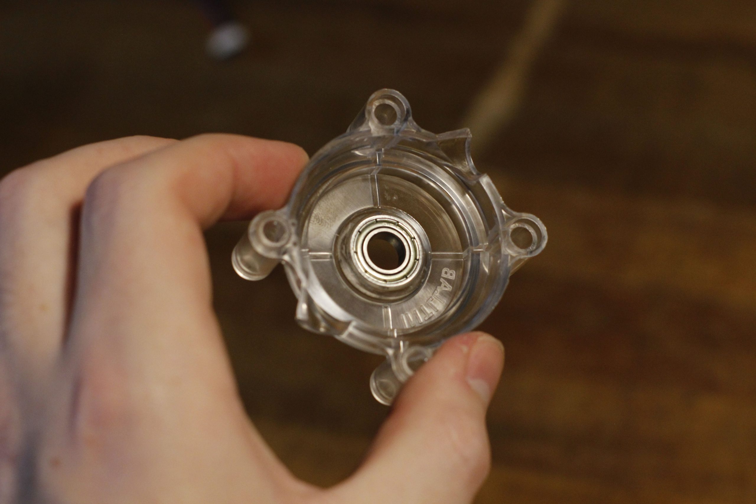
Description: A small, stepper motor peristaltic pump. This was the smallest pump under consideration, that boasted a correspondingly minimal design. The tubing is held in place with a top housing the snaps in place. There’s a D-Shaft that mates with the roller without using a set screw, and the roller assembly is mostly plastic. This part came with a fantastic mechanical drawing, a huge plus. There are four screws that bind the pump assembly to the motor. A very small bushing inside the housing that mates with the roller to maintain stability.
Sound: You can absolutely hear the rattling of the plastic rollers during operation. Since the tubing is in tension while it’s moving liquid, the release cycle kind of flings the roller causing it to rattle and make some noise. This rattling was completely suppressed when lithium grease was added to the internal mechanism.
This pumps size, and it’s silent operation when lubricated made it the winner. This exercise of ordering and returning pumps may seem like a waste of time, but I couldn’t get conclusive answers on how these different configurations would work though online research. It ended up saving me time in the long run to batch analyze these pumps before designing anything rather than have to do a third revision at a later date with a different newly discovered pump.
Design Overview Preamble


With the key components selected and the research phase concluded, I began working through the design process for the second iteration. The rest of this post will be an explanation for each of the component parts of the final design.
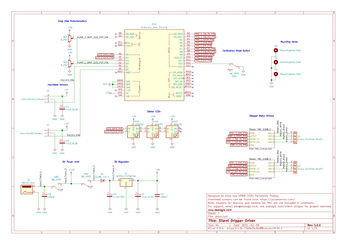
PCB Design
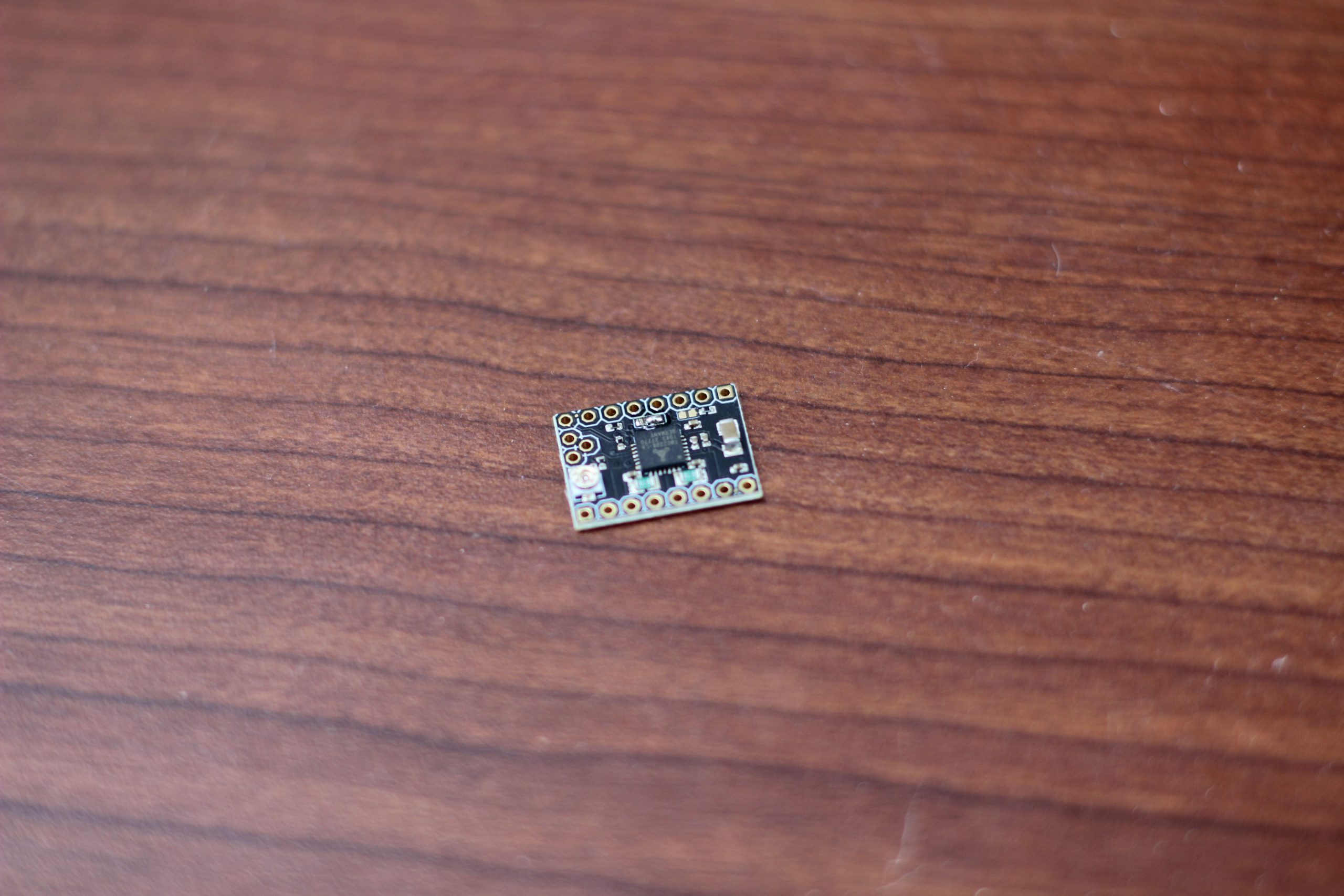
Creating the PCB was actually the least complicated part of the design, which is a testament to the overall complexity of this project. The TMC2208 breakout boards simplify things a lot, PCB is mostly just a host for the two drivers in an Arduino shield format.


The drivers are installed via sockets on the PCB, so they can be replaced if needed. The drivers are a bit sensitive, two were fried during the development process. One got too hot while tuning the drive parameters and one died for some unknown reason. They’ll be more about this later but when interfacing with these boards you should absolutely use the serial communication port to make sure they’re still responding.
Out of an abundance of caution, the drivers on the PCB were shipped with heat syncs installed. If you’re able to calculate and set the drive parameters of the TMCs correctly, and your load electrically is small, heat syncs can be overkill. In the final config for this build, the drivers got warm but never hot. I did find that these devices did get very hot using the potentiometer to adjust the RMS current, proceed with caution.

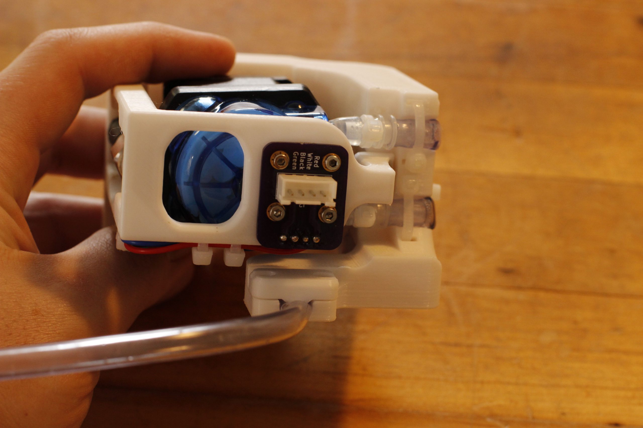
The PCB connects to the pumps via a wire with a 4 pin eXH JST connector on one end and 4 bare wires on the other. The connector end mates with a small and simple PCB inside the dripper. Using a four wire barrel plug would have probably been around the same cost, but this approach took up very little real estate inside of the dripper. Also, this is the same type of JST connector is commonly found in 3D printers, increasing the possibilities for recycling this design. They’ll be more later on ideas to extend this design but using a standard connector like this makes that slightly easier. To panelize these two designs down to a single PCB, this technique was used.


There are a few user interface elements as well. Ones I wished for the most after retrofitting the cadence PCB. Two potentiometers on the top, make it easy to tune the drive parameters in the firmware. As of the latest version of the firmware, these pots map the number of steps per drip, making it easy to precisely tune how big the water droplets would be. There’s a demo of this in the overview video:
The other UI elements are: three addressable RGB LEDs to communicate status back to the user and three switches. The switches connect the power on the DC inlet to the motor drivers, enable an onboard regulator and the third one is programmable in software.
Other notable parts of the layout are the larger traces for 12V power, and the decoupling capacitors everywhere to try and make the heartbeat sensor readings more accurate. Even though the TMC modules have filter capacitors on board, I learned a painful lesson while using the cadence PCB to drive the DC peristaltic pumps during the twitch performances of this installation. As was mentioned, the cadence PCB was meant to drive solenoids, not motors, so to cut cost, flyback diodes weren’t included. When using the board with DC pumps all of the leftover energy from the spinning rotor would dumped right back into the PCB and make the ground reference very noisy. The following is an oscilloscope reading of the heartbeat sensor, you can see the spikes during a pulse (and corresponding motor activation):
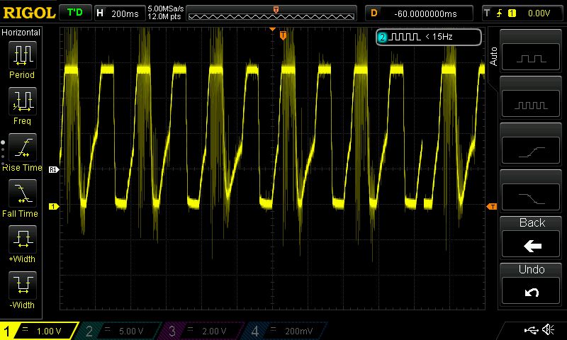
This caused intermittent problems when reading the heartbeat sensor. We tried the normal tricks to get around this. Adding capacitors to the motor terminals, twisting the wires connecting the driver and the motor and software filtering. No solution was stable. So at the last minute, I re-implemented the entire driver using the Adafruit Motor Driver Shield v2, and re-wrote the firmware to support this new hardware.


Because the shield had better electrical isolation, this did exactly what we wanted and was able to finish out the rest of the twitch performances without any more hiccups. This was a bandaid though, and the opportunity to fix this electrical noise issue was welcomed in the final revision.
If you’re interested in going deeper into the design or seeing the full BOM, the KiCAD schematic, layout and bill of materials have been on GitHub. The heartbeat sensors are connectorized, you could easily substitute in another analog sensor. The TMCs are also socketed and share a pinout with many other kinds of motor drivers. Personally I hope to recycle this design for a silent irrigation project in the future.
Software Design
The firmware to drive this installation is an Arduino sketch with three major parts.
- The algorithm to detect heartbeats.
- The code needed to configure and rotate the stepper motors.
- The management of the hardware UI.
I also implemented a very simple serial communication protocol to accept commands from a host PC. This is boilerplate, but when combined with a raspberry pi, enabled twitch chat to send !drip commands during the twitch performances of this project.
There are docstring and inline comments all over the Cadence Firmware repo. These next sections aim to clarify the larger ideas and themes seen in the code.
Heartbeat detection algorithm
The PulseSensor library code leaves a lot to be desired, particularly for applications that require multiple pulse sensors. A first-principals approach was implemented to support my needs here.
An interrupt routine is configured to fire at 1.736KHz. Each time it does, it reads in the current voltage of the pulse sensor.
If the value is above a threshold value (PULSE_START_READING_MIN_THRESHOLD), for a given period of time, and there hasn’t been a pulse detected recently, it sets a flag saying a pulse has been detected. There is a non resetting flag that needs to be cleared by the main() loop, and a resetting flag that will get reset by the ISR when it is detected that a beat has ended.
Outside of that, there is smoothing in the main loop to try and reject non-pulses. The sensor goes haywire when the hand is removed, and the behavior doesn’t seem to be deterministic either. This makes these sensors VERY hard to work with in this application, being able to detected a no-hand ended up eating a lot of time. If there is another revisit of this part of the project integrating something like a photocell, strain gauge, or capacitive touch sensor to detect the hand before trying to take a pulse reading could simplify the firmware dramatically.
Driving Motors (Using the TMC2208)
Even though the datasheet for the TMC2208 is short, and there’s already an open-source arduino library that implements the serial communication protocol used by driver, It took me a long time to understand how each of these parameters effected how the motors would rotate; to achieve silent, reliable, cool operation out the TMC2208.
The VACTUAL command initially seemed very promising. This lets you write serial commands out to the TMC to cause it to rotate, no need to clock out individual step pulses. This proved to be inconsistent at performing small rotations and was abandoned in favor of manually pulsing the step pin.
Through experimentation, it was determined that a higher microstepping value led to a quieter drive so in the production firmware, 256 microsteps are used.
More microsteps means more electrical pulses to actually move the motor. There’s a somewhat tight timing requirement as well, it can’t take more than about 300ms to form a drip because that would mean it could be possible to miss a heartbeat. So, the arduino’s relatively slow digitalWrite became a problem.
At 256 microsteps, I found it takes around 20000 pulses to rotate the motor enough to form a drip. That means we have to drive the step pin at around 66KHz. There are a lot of ways to generate this kind of signal with and Arduino, but the method was most reliable was to use the digitalWriteFast library to drive the pins, and timers to count pulses.
Because each pulse will cause the motor to rotate slightly, we need to be very aware of exactly how many pulses are clocked out. Per sensor/motor pair, whenever a heartbeat is detected in the main() loop of the sketch, a global variable is increased by the number of steps per drip. The ISR linked to TIMER2 firing at ~66Khz reads this count at every invocation and decides to pulse the step pin or not. If it does send out a pulse, that global variable is decremented by 1 until it reaches zero.
This worked well because the steps per drip value main() loop can change dynamically. This let’s the user slightly tweak how much water is moved per drip during runtime without having to re-upload firmware to the Arduino.
To configure the drive parameters of the TMCs, and to read status, I used the SoftwareSerial library. This caused some confusion because it turns out, under the hood, SoftwareSerial disables interrupts during the read and write phase of serial communication.
For me, this meant that the motors would stop spinning, and the values I read off of the heartbeat sensor would stop making sense. I thought this could be a power issue, maybe an electrical noise problem again etc. A lot of time was spent trying to debug this issue.
To get around this, the design decision was made to read status off of the TMCs during the setup() phase of the sketch. This gives us enough time to make sure the TMCs are configured correctly. From a firmware perspective, the best feature of these drivers is the ability to check if you’ve written config values without error, and I recommend you do this whenever possible. It makes it so much easier debug problems or strange motor operation knowing that your drive parameters are correct.
Not being able to use SoftwareSerial during operation sadly means that we can’t do things like read motor temperature during runtime. The most obvious way around this would be to use a hardware serial port, but unfortunately that was needed that for serial communication with the host PC. Using something like an Arduino Mega to get around this would be possible, but the design was already locked into the use of the Arduino Uno.
User Interface
Relative to driving the motors, implementing reading/writing from the UI elements was easy. I used my favorite arduino library of all time, FastLED to write colors to the three on-board LEDs.
On startup, the Arduino writes drive parameters to the TMCs. If this process fails, meaning there is no TMC attached, or the TMC is fried and not responding, a corresponding LED will turn red. If everything works as expected, the LED will turn green. Then, during runtime, the LEDs will blink purple while the motors are enabled and be off if they’re idle.
There are switches to control power delivery, and then potentiometers to control the drip size dynamically. A number of factors can influence the amount of water that gets delivered to the nozzle, including the length of the tubing attached to the pump and the current temperature of the room. Having these adjustment knobs in place makes it easy to compensate for these factors.
In conclusion, the software for this project is mostly an exercise in configure and control of the TMCs. Non-marlin examples of this are somewhat hard to come by, so it’s my hope that this example could be useful to others.
Mechanical Design
There were a number of rough edges that needed to be smoothed over in the mechanical redesign, but, in the aggregate, a similar design approach to the first iteration was used.


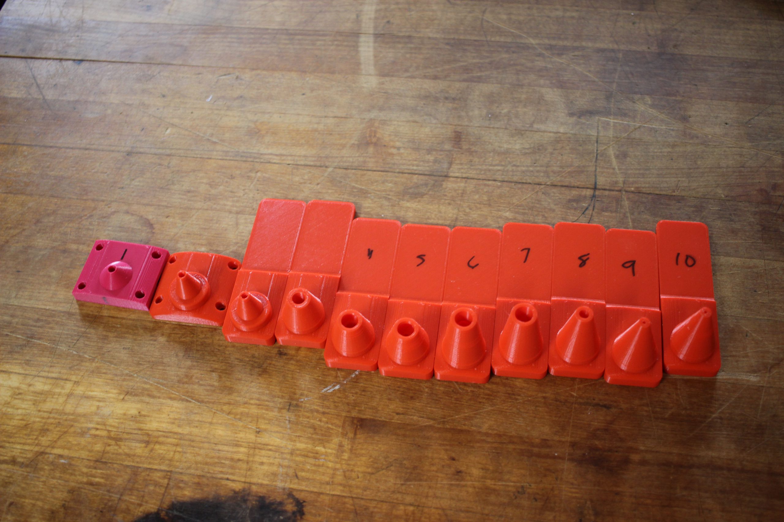
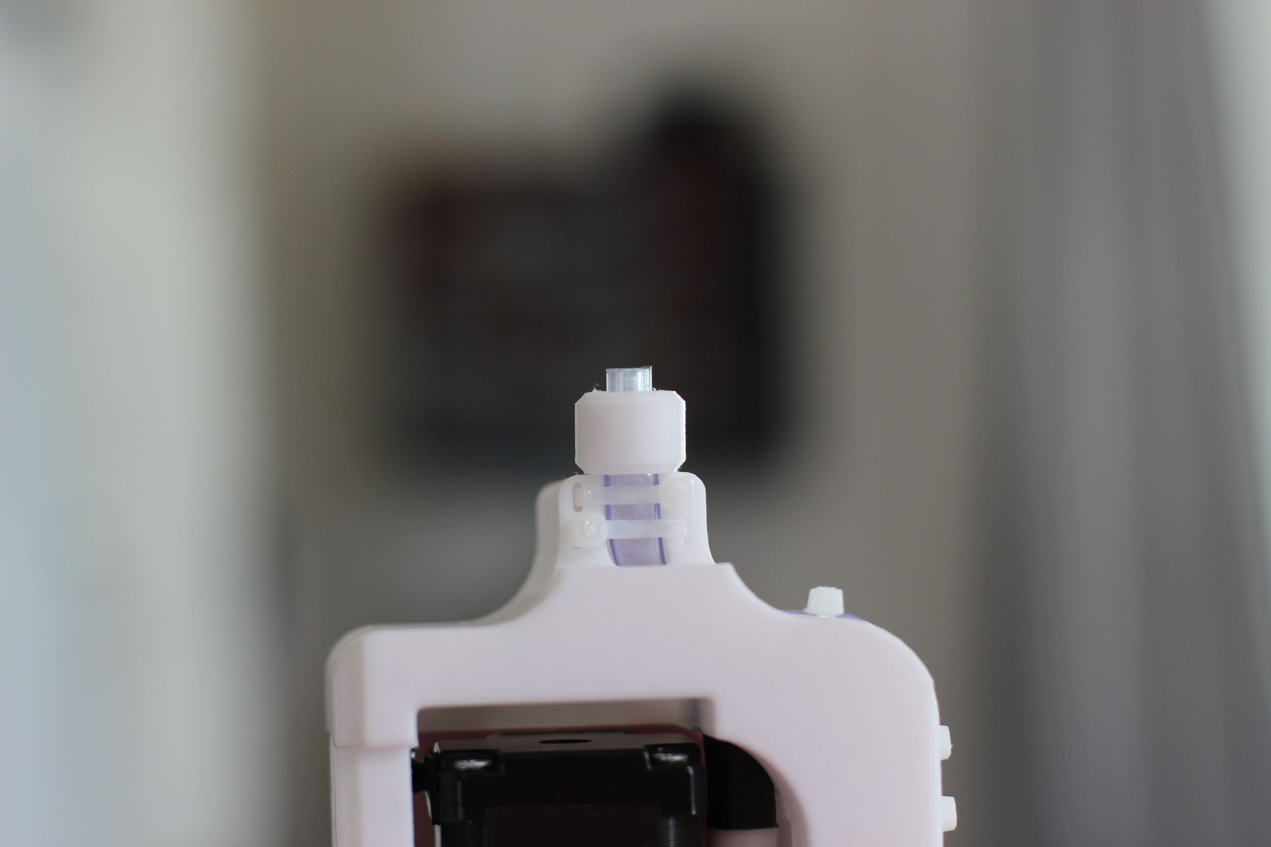
Since there wasn’t as much of a time crunch, I was able to spend a bit of time on the research and development of the different nozzles. I found that 3D printed PLA is totally capable of forming water droplets reliably and consistently even after thousands of droplets. For the nozzle geometry, there wasn’t any theory at all guiding me toward the final design. I’m sure that the shapes you see in industrial parts are designed with some theory in mind, it was pretty inexpensive to go the experimental route, quickly trying out different nozzle geometries. It took less than 200g of filament to arrive at the final nozzle geometry.
This meant that those bulky brass and plastic parts from the first design weren’t needed. This, and the fact that the new pump was a bit smaller meant that it would be possible easier to shrink the overall size of the second iteration.
From an assembly point of view, even though only a handful of these parts were going to be manufactured, I wanted to make sure the process was much cleaner that the first iteration. From the start, I wanted to have two separate components, one for the pump, wiring and plumbing and one for the housing, which I called the shell. This way the internal component could be a lot more complicated because it could be assembled outside of the shell. It also would mean that we could swap out the shell piece, which had the nozzle on it, with a different part if we ever wanted to do bigger drops or something like that down the road without having to rebuild the internal piece from scratch.

It did take several iterations if the internal assembly to get something working reliably. The tubing is guided through the internal piece so it never has to turn too sharply, which could cause a kinks over time.
It’s funny to me how it kind of looks like a lower intestine.
The XP88 ST01 has a different flow orientation that the original pump, and the mounting points on the pump weren’t conducive to the original approach of just bending the inlet tubing around 180 degrees. That original approach was also a hack, the inlet tubing doesn’t kink because it’s held in place by tension. Over time one would imagine that this tension could equalize either from the tubing deforming or the printed parts warping slightly. This would lead to the tubing kinking, disabling the dripper. Eight zip ties were used in the design to make sure that the tubing doesn’t move around while operating. You can see this phenomenon on video, but the tubing wants to wiggle around a lot once it starts moving water. I don’t know exactly what causes this, probably something to do with the pressure differential at either end of the tubing, but it did actually cause sticking noises where the tubing would wiggle around inside of the internal piece. Using zip ties stopped this from happening and made sure the tubing was firmly in place. The internal assembly is a moderately complex model, but the resulting product is easy to manufacture and assemble.


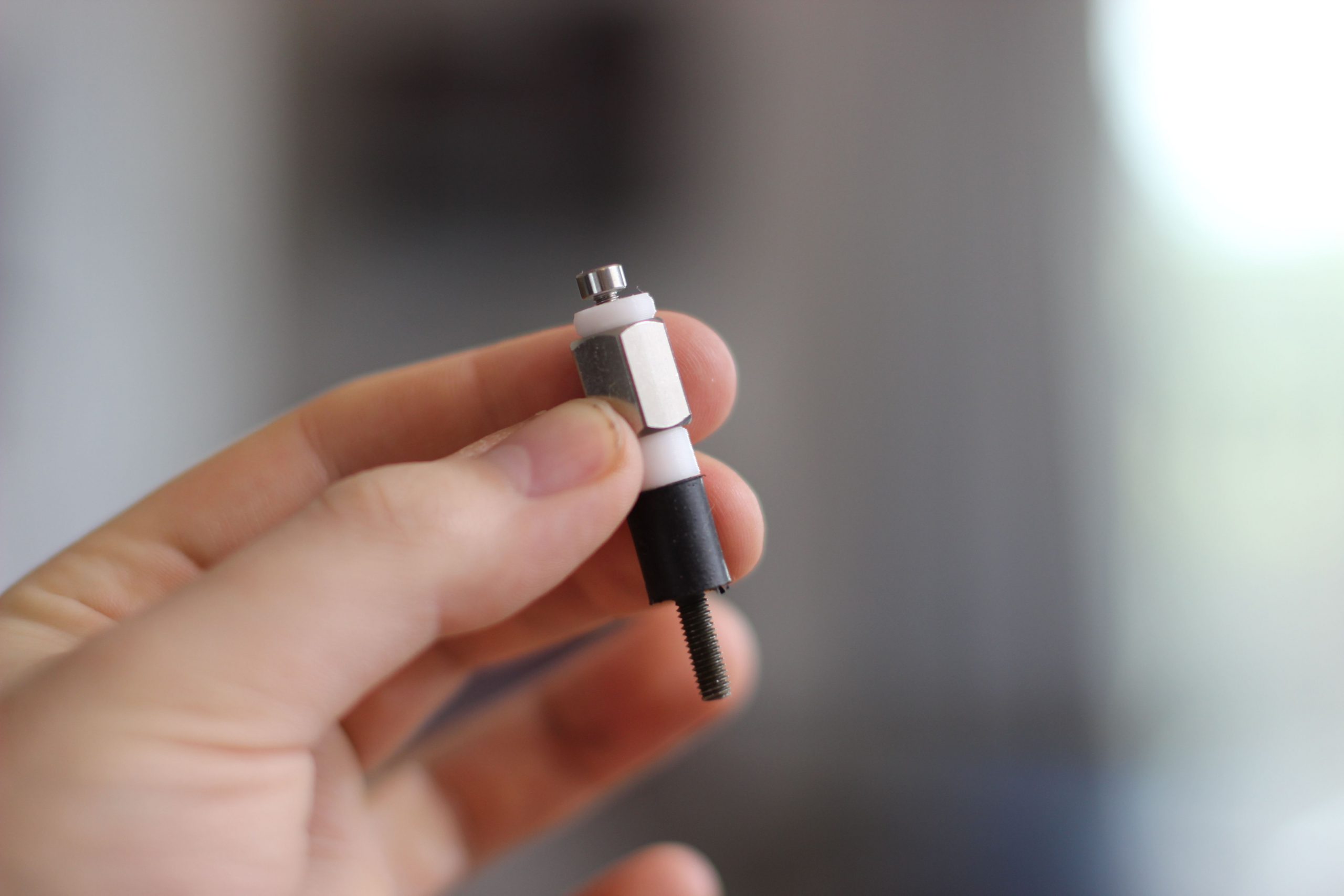
To try and prevent vibrations from going from the pumps into the housing, I used two rubber dampening mounts I got from McMaster Carr.
More zip tie slots are available for cable management inside of the dripper. There was plenty of space for this and I hate cutting cables too short because it makes the motors hard to re-use in other projects. The connector is firmly mounted in place with four m2 bolts.
To make sure the tube is cut to the correct length off of the bottom of the internal piece, a small ring is included equal in height to the length tube. It masks of the correct length of tubing so it’s easy to cut the output segment to length:
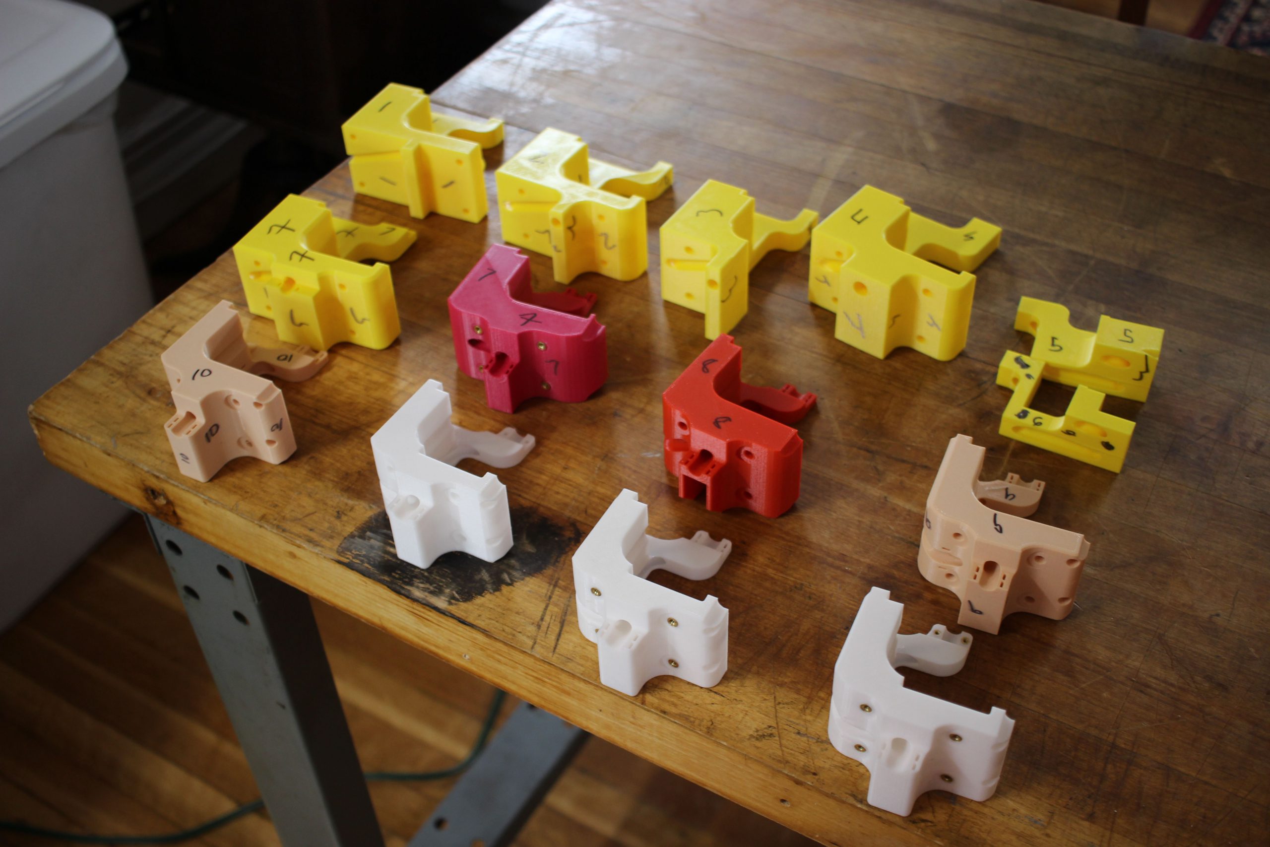
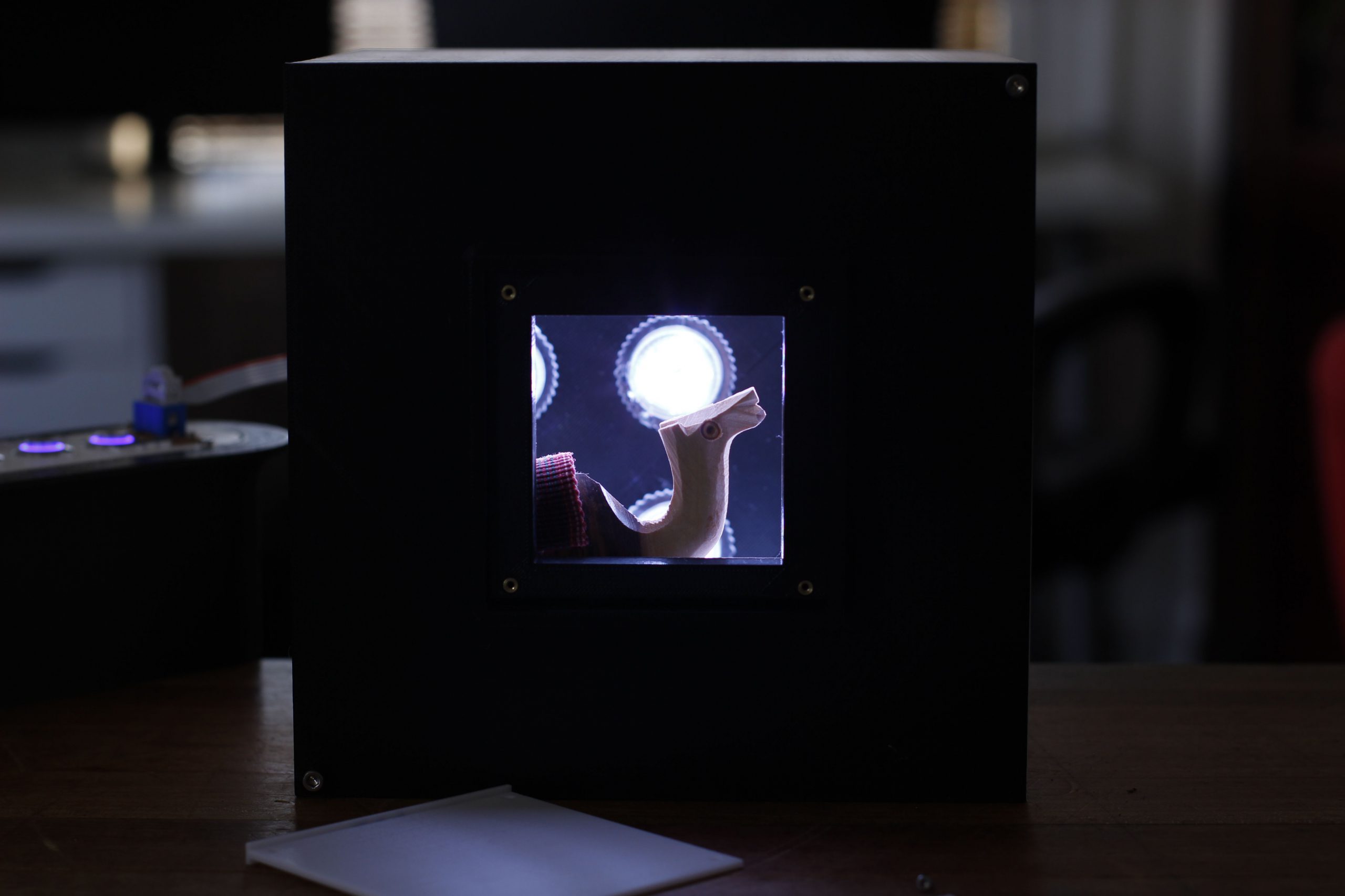
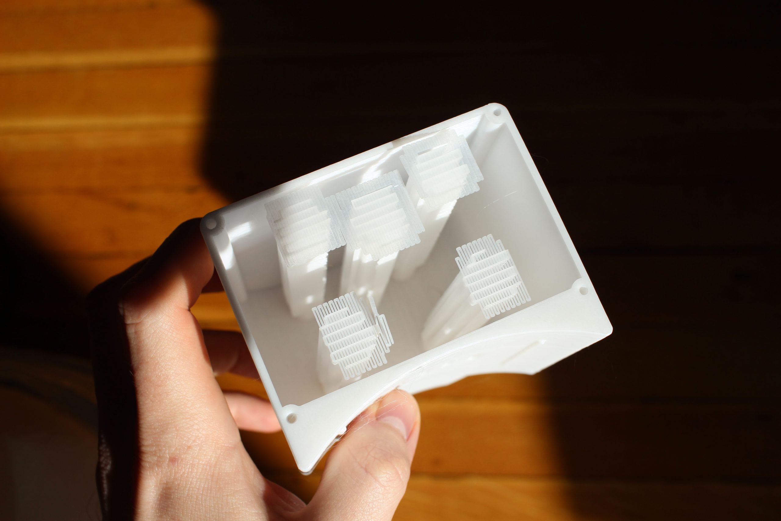
In early versions the shell walls were very thin, around 1mm. This contributed to an overall smaller footprint of the second iteration. These thin walls didn’t end up making their way into the final design because they were so thin that you could see the pump and tubing inside of the housing through the walls. I actually had to spend some time figuring out where the point of diminishing returns was for wall thickness and light leak. I got to re-use an old tool that I’ve never posted about, a box with 27 addressable 12V LEDs that is missing a side so you can install different printed pieces in to see how different light intensity looks behind the printed pieces.


After trying out five different thickness cross two different materials I ended up settling on 2mm. This is unfortunate because considerable time had been spent designing around those walls to be as thin as possible. Having walls as thing as all the way down to 0.75mm is possible, and still produced a stable and manufacturable design. It made the most sense to use white filament because it matched the rest of the parts used in the installation, but a darker color could reduce the overall size of the dripper in future revisions
Manufacturing
This project was the first time I used support enforcers in prusa slicer. These are great, because they let you model specific support regions in your CAD software, in my case Solidworks, and then import them, in place in the slicer.
This lets you be very precise about where the support material will be generated. For my parts, I wanted to make sure that the nozzle was printed onto supports rather than onto open air, but I didn’t want to use supports on the inside overhang because the printer was up to the job.
A part modifier was used to switch filaments mid print. This enabled using a black nozzle in the final design, creating visual cohesion across the two iterations.


Assembly Notes
An assembly video of one of the production drippers, is included as a time-lapse at the end of the overview video.
The most complicated assembly step, or at least the easiest one to get wrong is installing the brass threaded inserts.
I just use my soldering iron to do this but I know they make specific tips for this if that’s something you have trouble with.
There isn’t really a specific orientation needed for installing the zip ties, I liked having them all be the same direction, with the flat side of the tab flush with the part.
There should also be a light amount of tension on the tubing when you install it as well. I found that the tubing wants to move around when it’s being pulled on by the pump. If it’s not really secured in place, you’ll get noise from the tube sticking and unsticking to the internal piece.
Extensions
At the end of the day, this project accomplishes the pretty simple task of making water droplets quietly. I think the combination of technologies is interesting though, and I spent a lot of time in the research phase to make sure everything worked correctly. I have a few ideas for how this work could be extended:
- Because the TMC2208 breakout boards are a standard footprint, you could very easily swap in other drivers here. Say you wanted to make drips of something thicker than water, you could sub in the TMC2209 and use it’s stall guard feature without having to re-design the board at all.
- Outside of Marlin, I didn’t find many examples of people using the TMC library in their projects. I had a hard time understanding how the library worked, hopefully this will give someone a better jumping off point than I had.
Thanks for reading, again this project was such a rare treat.