
Edit: This project was completed hackathon-style in a matter of days. I’ve been working to optimize the design and sell kits, follow along here.
Here’s a (long winded) video overview of this project:
Background
Rendered desperate for VRAM by a forthcoming now released! stylegan-related project, I recently had to wade thermistor first into the concernedly hot and strange world of GPUs without video outputs to design a high performance cooler for the NVIDIA Tesla K80.
Too esoteric to game on, and too power hungry to mine cryptocurrencies with, the K80 (allegedly the ‘The World’s Most Popular GPU’) can be had for under $250 USD on ebay, a far cry from it’s imperial MSRP of $5000. By my math, the card is one of the most cost-efficient ways to avail one’s self of video ram by the dozen of gigabytes.
This sounds great on paper, but actually getting one of these configured to do useful work is a kind of a project in, and of itself. I’ll eventually get to this in the aforementioned upcoming post. Today’s topic however, is upstream of all that: the task of keeping these things cool.
Many of the Tesla cards, including in the K80, do not have built-in fans like the GPUs you and I know and love. This isn’t because they’re passively cooled, it’s because the typical installation has them trapped in server chassis that are themselves housed in forced air cooling racks inside of air conditioned datacenters. Intake and output pull conditioned air from the isles of data center through the cards then out the back of the rack.
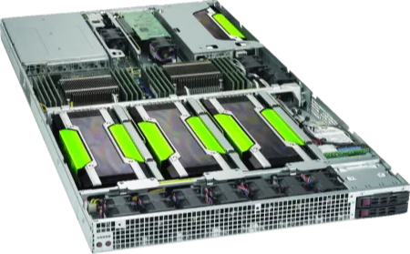

If you look online, you can find a few such examples of these configurations. I had a viewer pop into my twitch chat with a story of using these types of compute cards professionally and said that the topology in the previous pictures is par for the course.
Contradicting what I said earlier about these cards being hard to play games on, given the current silicon crisis, people online are taking the plunge, trying to get these cards working alongside a CPU’s integrated graphics stack. The idea being that the work is offloaded to the compute card and then displayed via the motherboard output (as the K80 etc have no video outputs).
These brave gamers are running into the cooling issue as well. Because of this, there’s kind of been renaissance of DIY cooling solutions for these cards.
However, many of these implementations fell short of my requirements. I needed a cooler that could:
- Have a feedback loop to automatically ensure the fans weren’t deafeningly loud while the card was idling.
- Support having two cards installed side by side (many existing designs were too big to be able to do this),
- Reliably cool both cards, with both cores in each card drawing the full 175W TDP.
- Be made out of parts I had around my studio (fans not included).
Many existing designs either were too big, or didn’t look like they could push enough air to meet my requirements.
A few people have pointed out to me that I should consider water cooling the cards as there are cooling blocks available on amazon. This is a great idea, and would certainly be quieter than my final implementation. Early on I decided against this because this would have been my first foray into water cooling, and the project that these cards unlocked was too time sensitive to allow for replacement parts for my server to arrive in the event of a disaster. If you go down this road after reading this post please drop a comment or send an email.
After a few iterations, and some cool MicroPython I’ve got a design worth publishing.
Early Iterations
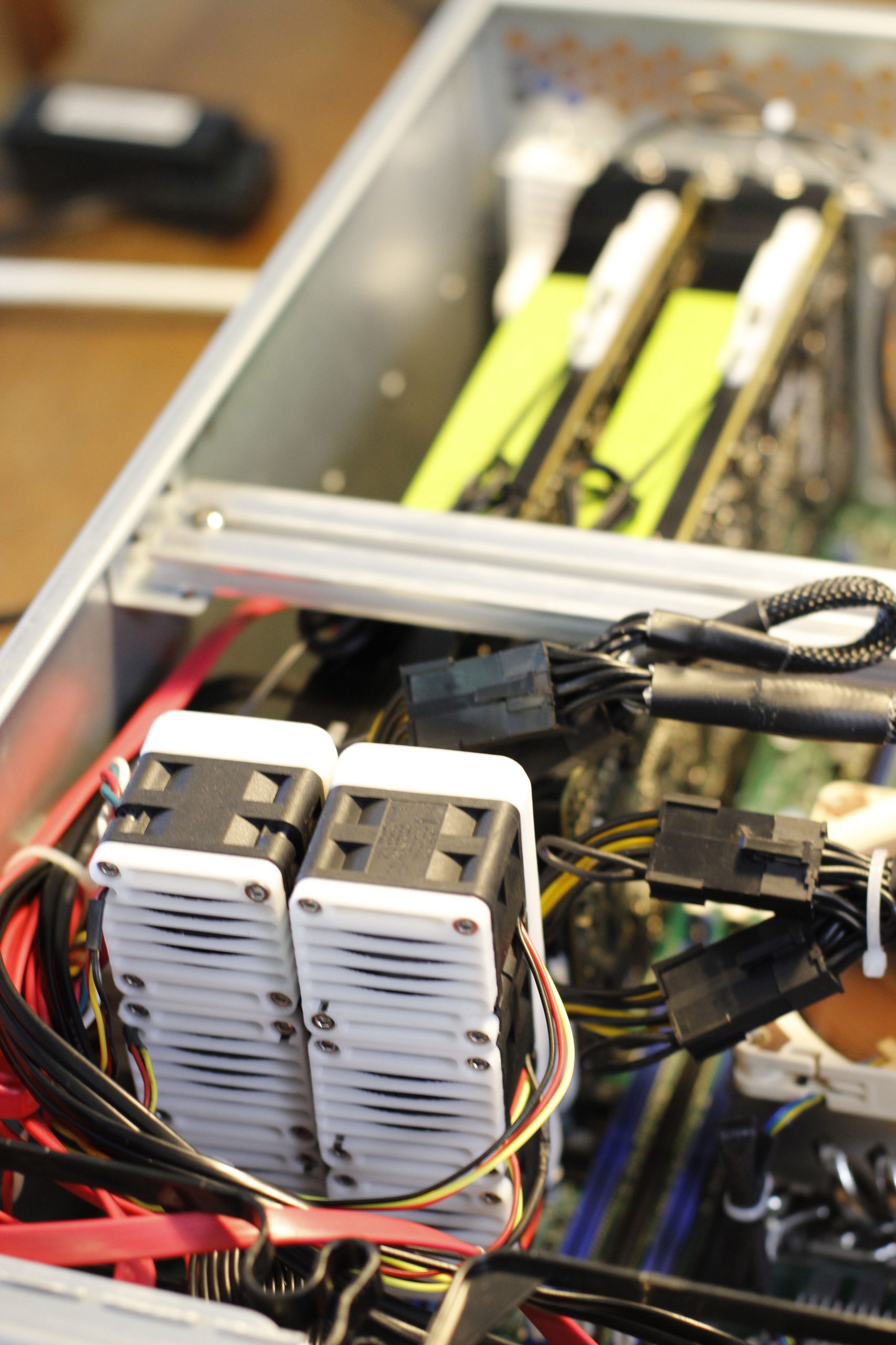
The first three versions of the design were iterations on the concept of using 3D printer part-cooling blowers as the fans, with a DC/DC boost converter to regulate speed. This design got me up and running, and taught me a few valuable things about how the cards want to be cooled. Here are a few photos of these versions:


These are prototypes. It should go without saying but doing speed control this way is a total hack and, anyone that has worked with these cards before would be able to authoritatively say that those fans don’t have what it takes to be able to cool the card.
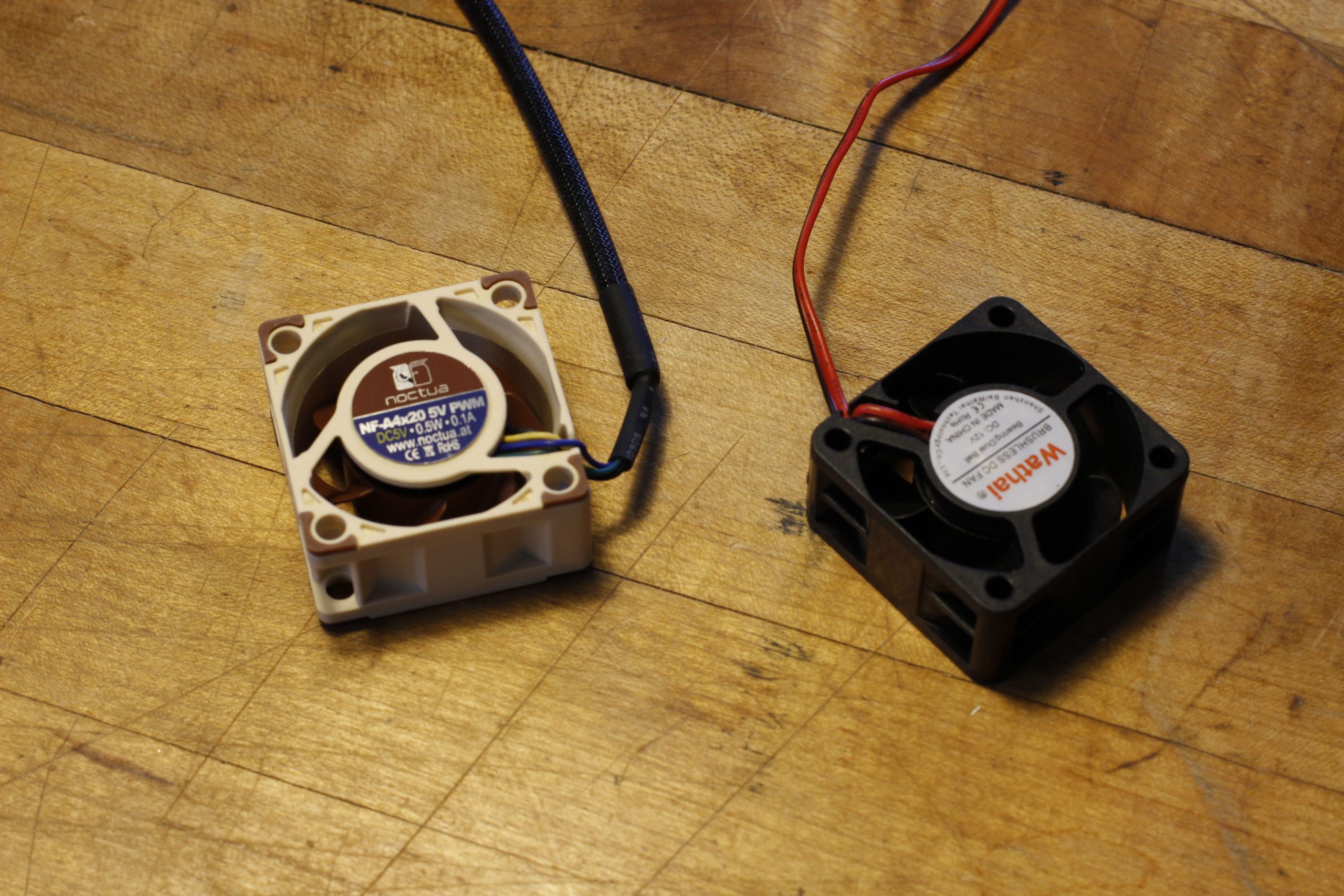
These fans rotate at 5500 RPM, and are only rated to be able to move 3.23CFM (cubic feet of air per minute). To contrast, the fans I eventually settled on can rotate their blades at a startling 9200RPM, and can move air up to 17CFM.
Still, these designs were enough for the early days of the project, and kept the hot-side (see video for term) GPU inside a single card perfectly happy. I prefer to design this way, the first iterations being haphazard meldings of various proof of concepts later smoothed over and manicured into a final revision.
Final Design
If you’re interested in building one of these coolers for yourself, the designs, schematics and code are all available on GitHub.
There’s a top-level organization for the whole project, and sub-repos for the:
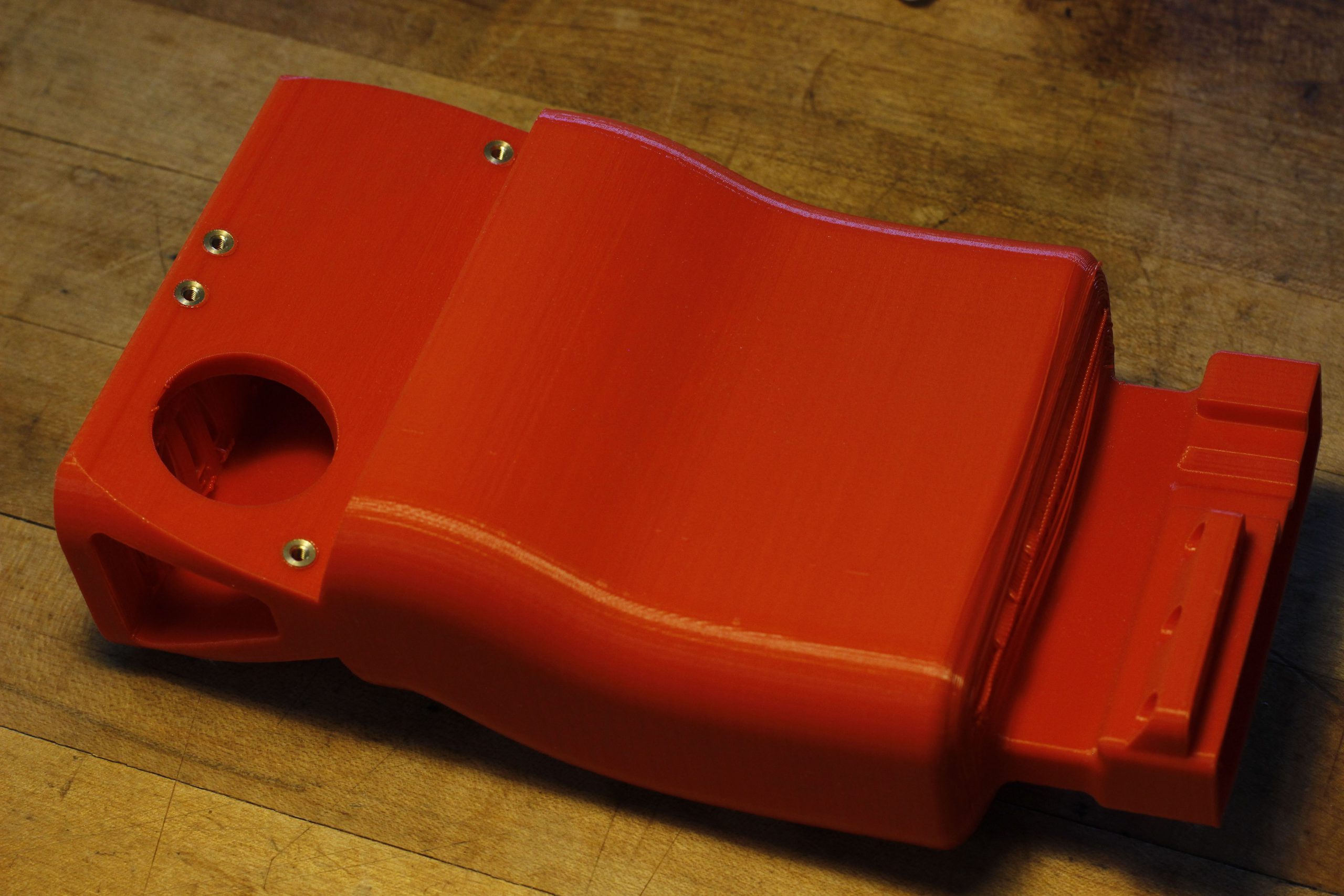
Here’s the best picture of the single piece:
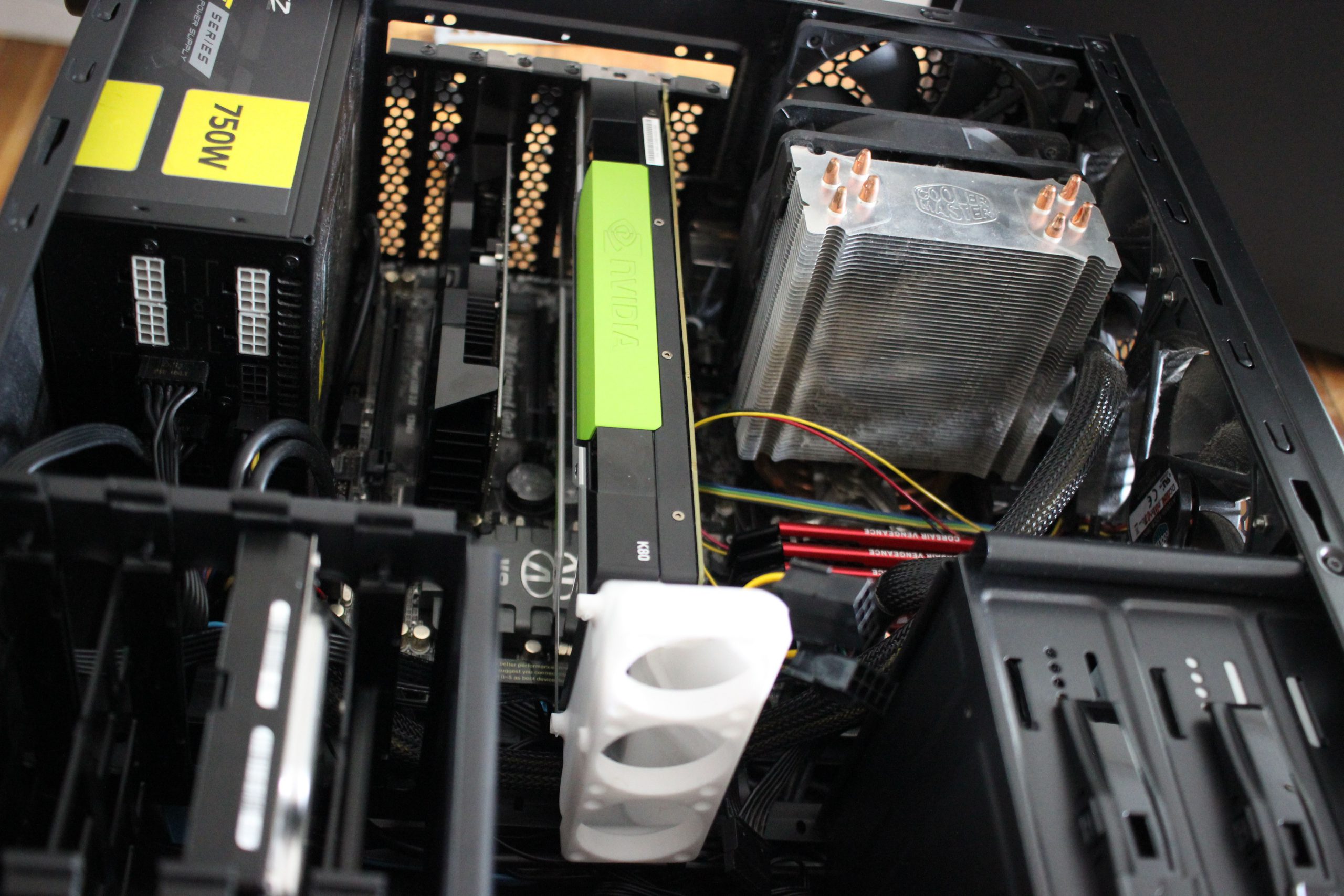
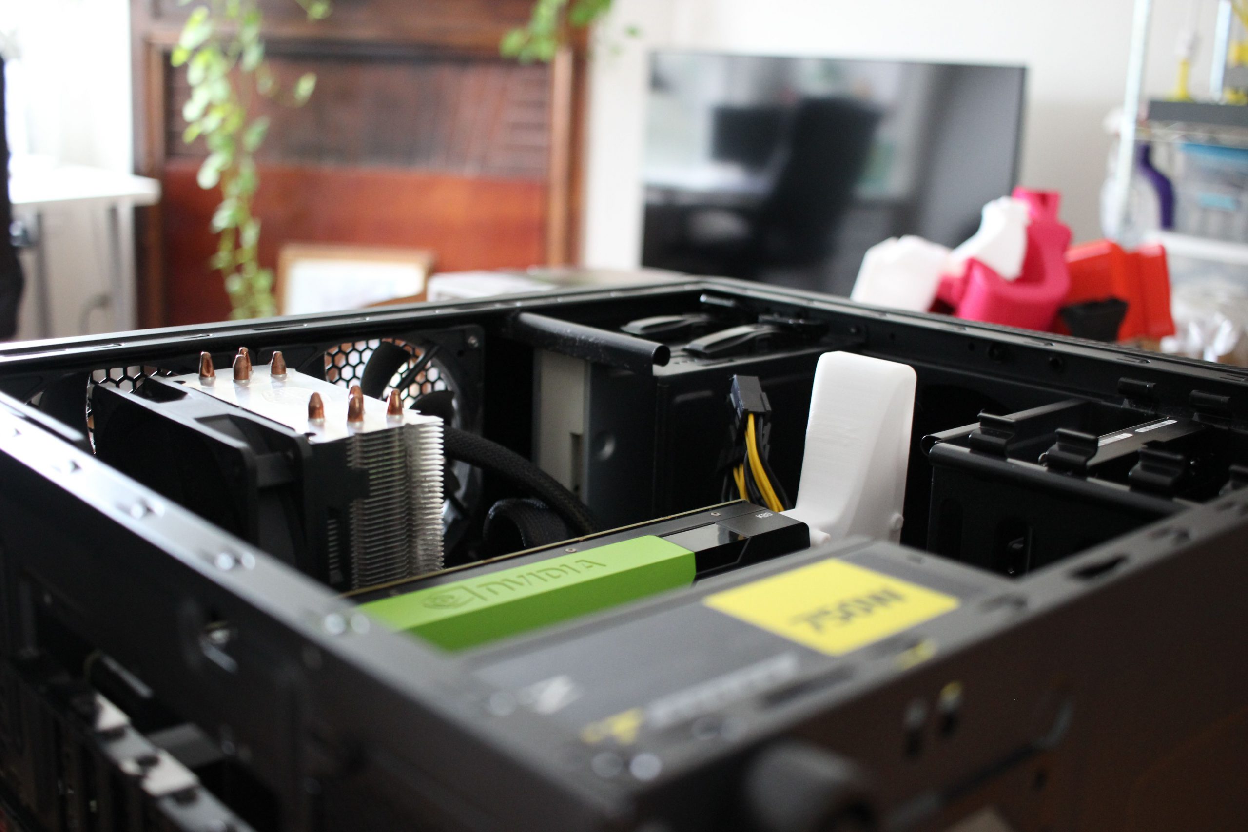
 Here are a number of photos of assembled design, both on it’s own and installed:


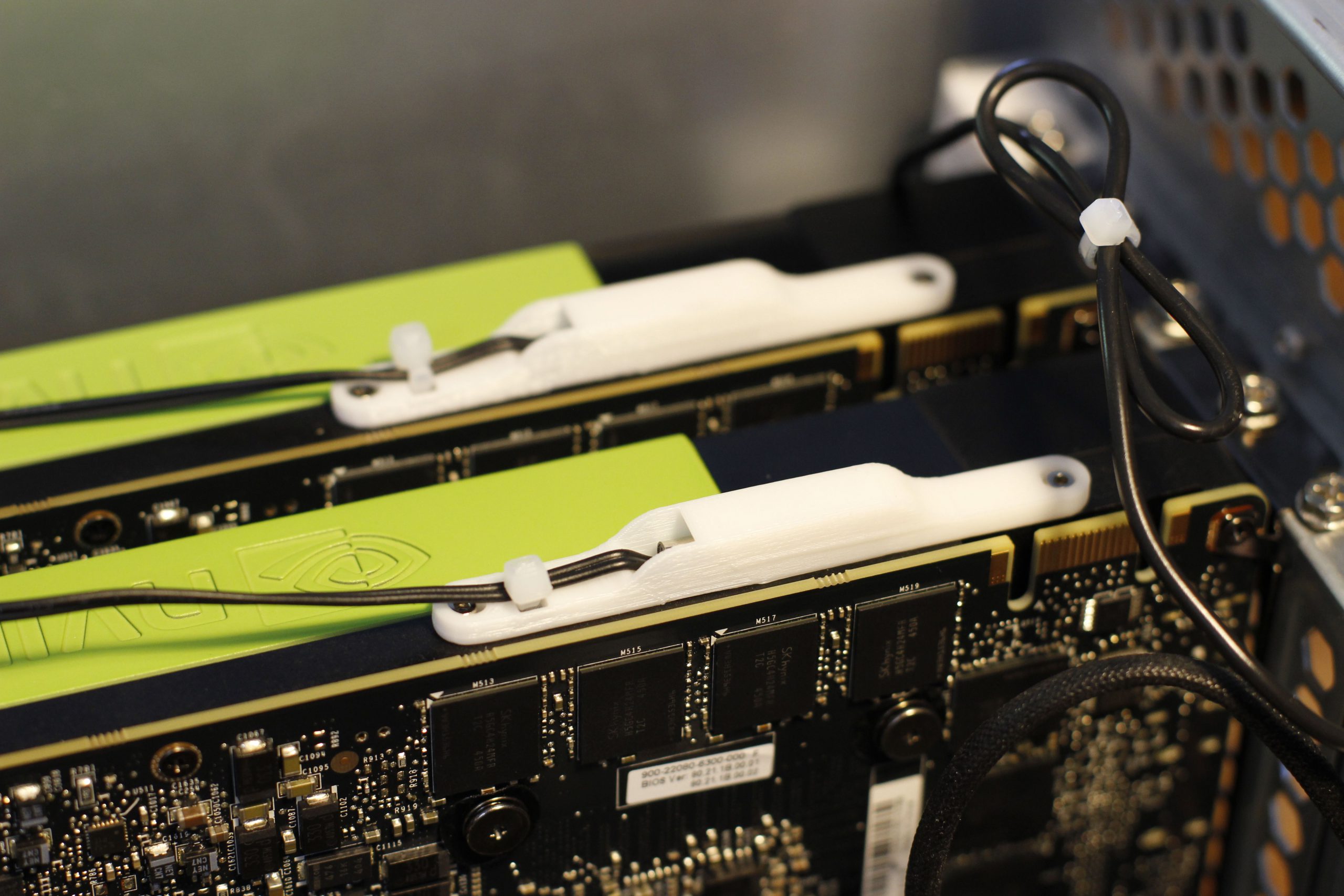
Here’s a close-up of both cards + coolers installed:
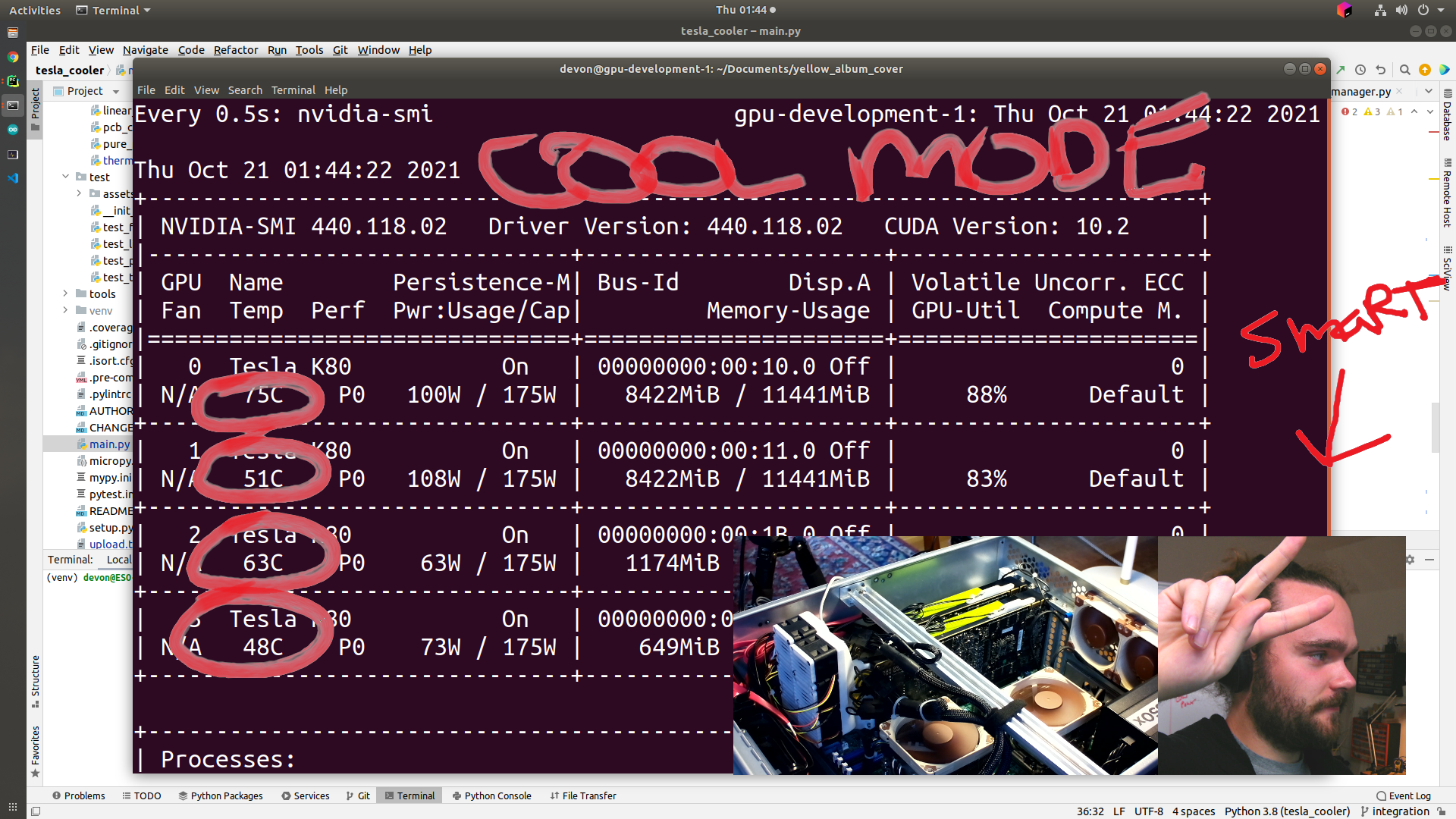
The theory of operation here is similar to most all fan controllers, with a few differences worth highlighting. The driver PCB can support up to 6 fans and two thermistors, with the idea being that user can spin up a single PCB and cool two GPUs. The thermistor is bolted on to the outside of the GPU housing on the hot-side of the GPU. Experimentally I found that these readings were quite different than the core temperature of the GPU as reported via nvidia-smi, so there’s a correction in the firmware. As this temperature increases, the fan speed increases. When the GPU is very hot, all three fans spin as fast as possible. When the GPU is idling (so sitting at around 50 degrees C), only one fan per cooler will be spinning. In between these two bounds an algorithm is used to try and balance airflow and fan noise. The operating concept of this algorithm (detailed more completely later in this post) is that two fans spinning slowly is better than a single fan spinning quickly.
Here’s a photo of the nvidia-smi output with both GPU running at max power. The coolers are keeping things running nice and cool.
Speaking honestly, the sound level produced under a heavy load still leaves a lot to be desired. Idle noise levels are fine, but under full load, with all fans operating at near 100% power, things can get quite loud. Swapping the 9.2k RPM fans for some slower, quieter ones is something I’ll revisit when I’m done working through the parent project that requires these GPUs. I have a few smaller fans in the 40mm variety that are on my list to try:
The rest of this post is going to be an deeper explanation of the implementation and design challenges for each of the component disciplines in this project.
Mechanical Design + Manufacturing
The manifold printed out of PLA, you’d think this would be a problem because the GPU can easily reach 80 degrees C, but then you’ll remember the whole piece is being actively cooled. Even with the design printed in black PLA, that big, heavy, cantilevered thing, I never ran into issues with sagging. Even in the heat of the summer.
Like is detailed in the overview video, the heart of the design is a loft operation that joins the K80 fan inlet with the fans. The great thing about this is that it’ll be easy to update this design in the future by just changing the mates between these two interfaces.
The top of the cooler is about as far away from the motherboard as your typical CPU cooler. I found that a K80 + the cooler could fit inside of a standard ATX case given you had enough clearance off of the rear of the card to fit the manifold. This is a happy accident, as I was designing this specifically for server chassis that have a lot of room.
The fan guards are kind of redundant. They probably inhibit airflow, but the fans are spinning so fast that any kind of cable or finger that wanders into their blades is going to get totally shredded. Like a few other things in this project the inefficiency here is overcome by an imbalanced amount of power.
Everything was designed to be able to be printed without supports. This soft requirement partially informed the angle between the fan mount and the K80 inlet.
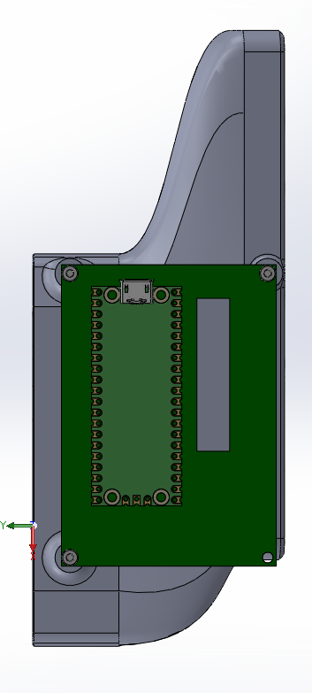
The design could be a little more compact, but I knew it needed to hold a 50mm x 70mm piece of perfboard for the electronics. If the PCB gets smaller in future iterations, it would be worth it to spend an afternoon making this piece little smaller as well.
My favorite part of the mechanical design is how light and printed part is.
The walls are only a single millimeter thin, but with all of the curvature are still quite rigid. The small size meant that design iterations were inexpensive in time and materials, a rare treat in mechanical design. Here are a few more photos of the mechanical assembly process:


Electrical Design + Manufacturing
The electrical design is as simple as it gets. One NMOS driver per fan, pulldown resistors for the gates of FETs, and pullup resistors for the thermistors.
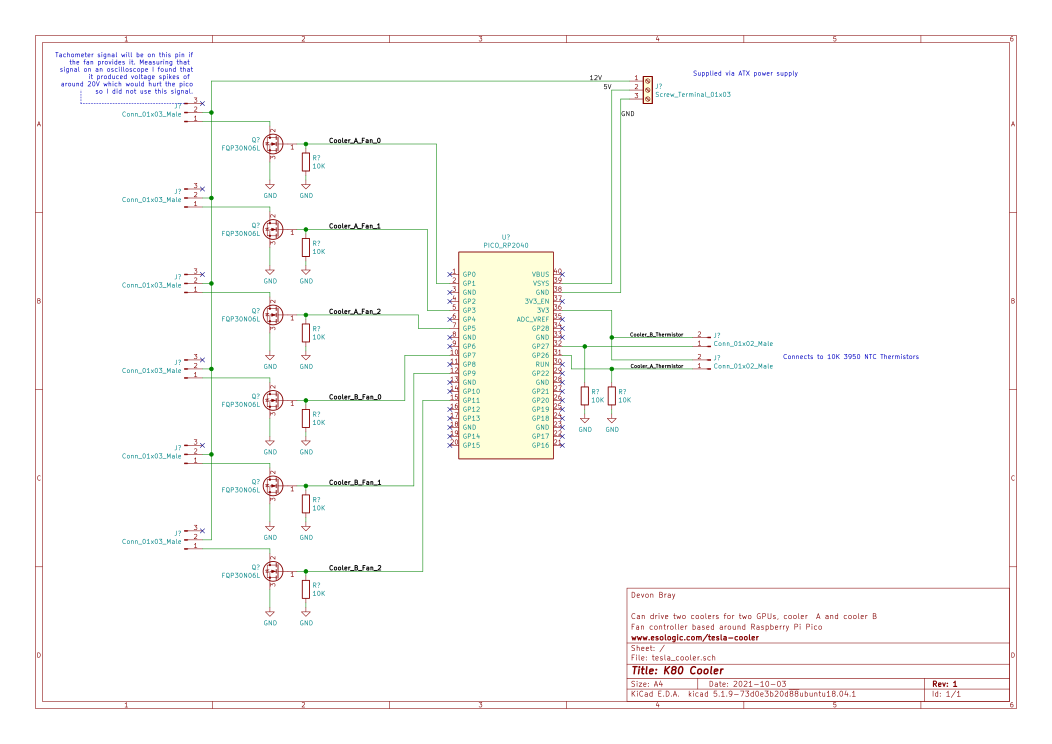
These thermistors have loitered patiently around the studio for a long time, waiting to be used in a project. They’re probably a little bit overkill for the design, hopefully their waterproof functionality will remain untested. The measurement range is -25C – 125C. We’ll never hit the lower bound, but the upper bound is theoretically possible if the fans fails. The K80s have pretty sensitive thermal throttling, and lock up long before getting that hot but you never know. Maybe in future iterations it would make sense to pick out a sensor that could go a bit hotter.
The K80s have temperature monitoring built in, and it should be possible to have the OS control fan speed based on these values. I decided against this because of the virtualization setup I was going to be using the cards in. They might only ever be exposed to the inside of a docker container, so that would mean that container now has to drive the fans as well. The standalone approach here is more portable.

It also wouldn’t be difficult to add more thermistors. The bolt pattern on the K80 that the thermistor is mounted on with has space for two thermistors per card. This could yield a bit more optimization but wasn’t worth it for the foreseeable future.
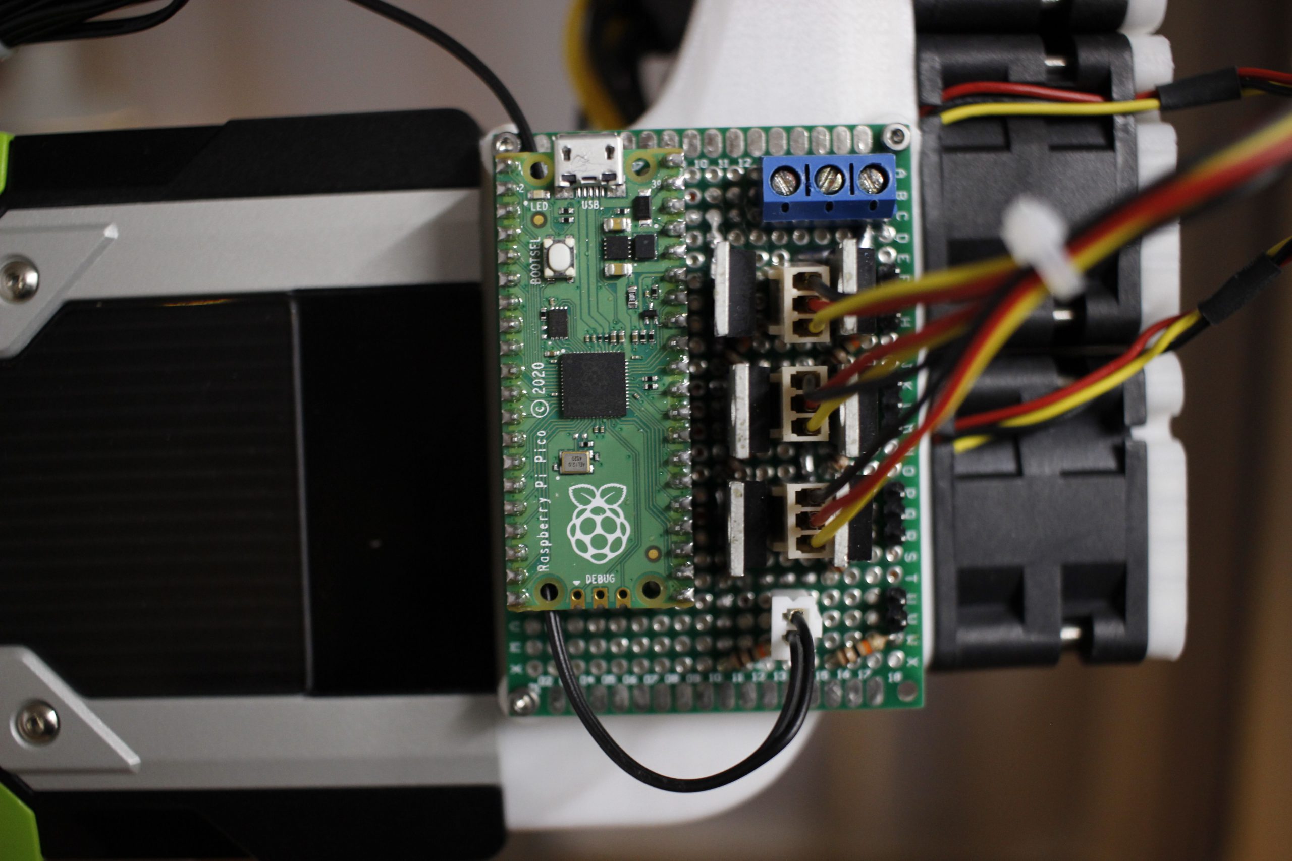
No custom PCB for this project, didn’t want to wait the extra time, and I have so much perfboard lying around. It was mentioned in the previous section, but decreasing this size could make the whole cooler more compact. Using the castellation on the Pico, and SMD FETs could decrease the envelope significantly as well and would be one of the first things I touch in a second revision.
Software Design
Using the Raspberry Pi Pico for this project was absolutely overkill but I purchased one at launch and hadn’t used it in anything yet so decided to go for it here.
Micropython is the real deal. I’ve been working a python day job for a number of years now and it is so refreshing to be able to use some advanced programming concepts on an embedded platform, rather than run back the Arduino greatest hits. Because your code can mostly run either on the embedded chip or on your PC, this opens up things like unit testing, style checks, type hinting etc. In my experience, the DIY embedded world has a particular aversion to unit testing, so I was very pleased to be able to write pytests for the library code for this project.
The repo should give you an idea of my toolchain here to get code onto the Pico. I got lot of mileage out of rshell, particularly rshell -f. This command lets you run a series of rshell commands within a text file. The file I have in the repo connects to the pico then locates and uploads only the files that should go into the pico (ignores linters, dev scripts etc). You can easily then have the script drop you into a repl for debugging etc.
Sensor feedback is achieved using a simple implementation of a fan speed curve; fan power is increased with temperature. Studious readers who work through the stream archive will notice that I try to implement PID control. The issue I ran into here was that the system had to be heavily dampened because it takes a while for fan increase to lead to a measurable temperature decrease. I also found it overly complicated to implement the idling detection using PID, I tried to keep a long temperature history but things were not working out so I switched to fan speed curve.
The fan power function is something that I’m proud of. This is a way of abstracting out the individual speeds of the fans into a single float between 0-1 to denote fan power.
To understand how this works let’s walk through a canned example:
Say you have 3 fans that are capable of 100 different speeds, 0-100.

Asking for 0.5 power is translated into asking for a total speed value of 150. This number comes from multiplying the power float by the maximum output power (300, 100+100+100).

That value of 150 can be reached in a number of different ways by the 3 fans. Let's take the most simple example:

* Fan 1 = 50, Fan 2 = 50, Fan 3 = 50

You could also achieve the total speed value as follows:

* Fan 1 = 100, Fan 2 = 25, Fan 3 = 25
* Fan 1 = 100, Fan 2 = 45, Fan 3 = 5
* Fan 1 = 25, Fan 2 = 75, Fan 3 = 50

Any combination of speeds that adds up to 150 is valid. But how do we pick the most optimal number? This is where the weighing function comes in.

Speed ranges are weighed based on how much noise they produce. Continuing our example:

* Speeds from 0-25 weigh 0      <- Makes no noise
* Speeds from 26-50 weigh 1     <- Makes some noise
* Speeds from 51-80 weigh 2     <- Makes a lot of noise
* Speeds from 81-100 weigh 3    <- Makes the most noise

So, if we weigh our combinations from before we get the following:

* Fan 1 = 100 (3), Fan 2 = 25 (0), Fan 3 = 25 (0)       Total weight = 3
* Fan 1 = 100 (3), Fan 2 = 45 (1), Fan 3 = 5 (0)        Total weight = 4
* Fan 1 = 25 (0), Fan 2 = 75 (2), Fan 3 = 50 (1)        Total weight = 3
* Fan 1 = 50 (1), Fan 2 = 50 (1), Fan 3 = 50 (1)        Total weight = 3

This gets us most of the way there, it correctly says that the second config shouldn't be chosen.

We should make the consequences for increasing to the next range more severe. If we raise the original weights to the 3rd power, and recalculate things start looking very how we want:

* Fan 1 = 100 (27), Fan 2 = 25 (0), Fan 3 = 25 (0)      Total weight = 27
* Fan 1 = 100 (27), Fan 2 = 45 (1), Fan 3 = 5 (0)       Total weight = 28
* Fan 1 = 25 (0), Fan 2 = 75 (8), Fan 3 = 50 (1)        Total weight = 9
* Fan 1 = 50 (1), Fan 2 = 50 (1), Fan 3 = 50 (1)        Total weight = 3

Nice! Sorting by min weight we correctly get the 50/50/50 scenario. This also extends to trying to get total power of say, 50:

* Fan 1 = 50 (8), Fan 2 = 0 (0), Fan 3 = 0 (0)          Total weight = 8
* Fan 1 = 25 (0), Fan 2 = 25 (0), Fan 3 = 5 (0)         Total weight = 0
Check out the source code for the actual implementation. Instead of “Speeds” like in the example, I am using duty cycle counts for the PWM pins. It was very fun to come up with this idea, then implement it on stream. That archive is here.
Breaking up a number into it’s potential sums of a given value is called integer partitioning. Turns out this is actually a well known CS problem and has a number of different implementations online. Problem is here is that once you have a large number, the number of combinations to make up the sum becomes massive, way way too bit to be done on an embedded processor like the rp2040. Because of this the implementation I landed on has a few shortcuts but the core idea is still there.
This is working great, it’s very satisfying to hear the fans kicking off when idling.
Abstracting out the fan curve function, revisiting PID control, and adding more fidelity and testing to the fan power algorithm are all things I would revisit in a next iteration. Again though, the level of software here is mostly overkill, an exercise in trying out the Raspberry Pi Pico and MicroPython.
Afterward
This project was my first venture into the world of engineering live streaming. I have been such a massive fan of scanlime since discovering the channel a number of years ago and have been keen to try out the streaming thing for myself. This whole design; the mechanical design, the electrical design and all of the programming happened live in front of a very small audience. Because you’ve read to the afterward, you get to see a secret archive of this stream in all of it’s chaotic glory:
There are timestamps, so you can skip around to the sections of interest.
Imagine my shock at actually enjoying this process! It’s no secret that my favorite way to publish my work is via blog posts. I’ve always struggled with finding a stylistic voice in video editing, and have made it a habit to record the process, leaving me with show-and-tell style videos after the fact rather than process demos. Livestreaming the whole thing solves this issue.
Next time a project comes around that is ripe for streaming I’ll be sure to post more about it on this blog and on YouTube. This first project was more experimenting with the medium than anything, so next time a project comes around it’ll be a more formal and concise process. I’ll be sure to send an email with those plans as they develop.
Thanks for reading! Please shoot me an email if you end up building one of these coolers. I’m interested in seeing how it performs outside of my studio.
Nvidia Tesla K80 24Gb Gddr5 kits?
Yeah this’ll work with the 24GB model.
Can email pleas.
Yeah — dev@esologic.com
Great job! And thanks for sharing the code on Github. Do you think this might work for a P100 as well?
I have been working on a new design that is compatible with K80, M10, M40, M60, P40, P100. Unfortunately this approach was not compatible with more power hungry cards.
THIS!!! Is what I have been searching for. I am a Veteran and a hobbiest and have acquired three of the K80s to keep my mind busy. I know this is an old post however, I’ve not the equipment to make these. Would you be up to the task to make three of these, pretty please 🙂
Hey Jay! I am working to make a commercial version of this project now. Email me at dev@esologic.com, and I’ll send you a prototype when they’re ready for testing.