So here’s a video:
So pretty easy but important step here. For a while I’ve known that I need to have some more feedback from the robot that just LED brightness levels on the controller. This VB program allows me to get analog values from the vehicle and interpret them in any number of ways. You can download and run that program HERE, and like I said in the video I’ve refrained from going open source with my VB programs in the past because they’ve never really had any polish to them. But now I think it will be good to keep this all open.
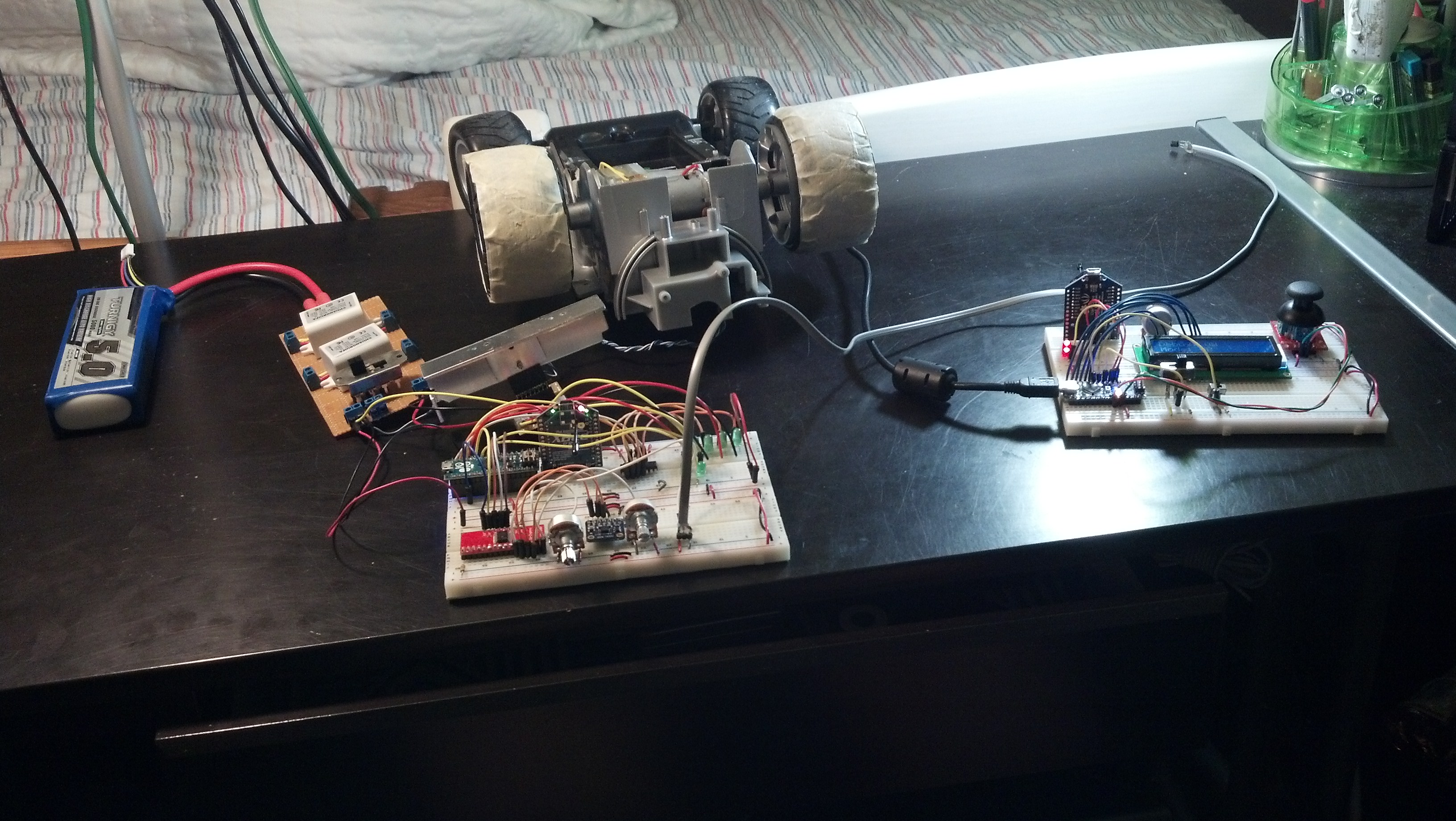
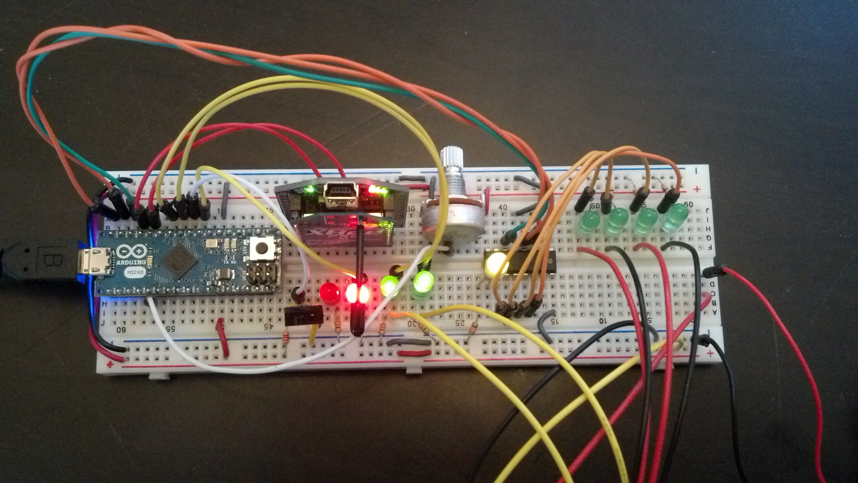
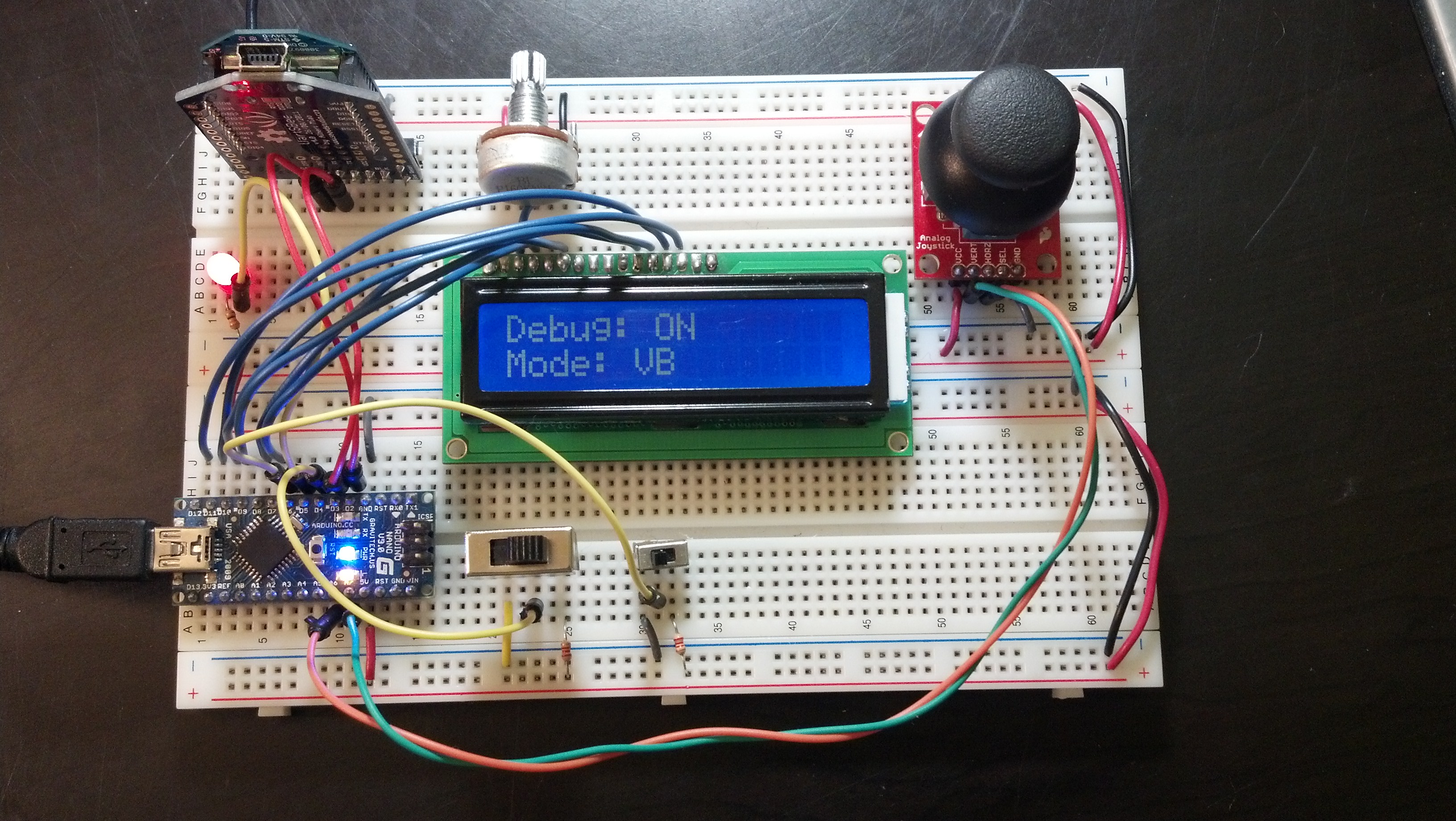
I also added a 16 * 2 character LCD to my controller. I’ve sacrificed the 6 pins because hopefully in the long run it will be a better experience for the user. I may go back, but for now I’d rather build around something that’s a little more constraining as it will force me to innovate a little bit more. Here’s a picture of the new controller:
Here’s the program:
|
1 2 3 4 5 6 7 8 9 10 11 12 13 14 15 16 17 18 19 20 21 22 23 24 25 26 27 28 29 30 31 32 33 34 35 36 37 38 39 40 41 42 43 44 45 46 47 48 49 50 51 52 53 54 55 56 57 58 59 60 61 62 63 64 65 66 67 68 69 70 71 72 73 74 75 76 77 78 79 80 81 82 83 84 85 86 87 88 89 90 91 92 93 94 95 96 97 98 99 100 101 102 103 104 105 106 107 108 109 110 111 112 113 114 115 116 117 118 119 120 121 122 123 124 125 126 127 128 129 130 131 132 133 134 135 136 137 138 139 140 141 142 143 144 145 146 147 148 149 150 151 152 153 154 155 156 157 158 159 160 161 162 163 164 165 166 167 168 169 170 171 172 173 174 175 176 177 178 179 180 181 182 183 184 185 186 187 188 189 190 191 192 193 194 195 196 197 198 199 200 201 202 203 204 205 206 207 208 209 210 211 212 213 214 215 216 217 218 219 220 221 222 223 224 225 226 227 228 229 230 231 232 233 234 235 236 237 238 239 240 241 242 243 244 245 246 247 248 249 250 251 252 253 254 255 256 257 258 259 260 261 262 263 264 265 266 267 268 269 270 271 272 273 274 275 276 277 278 279 280 |
//Serial Handshake declaration #include <string.h> // we'll need this for subString #define MAX_STRING_LEN 100 // like 3 lines above, change as needed. const char EOPmarker = '.'; //This is the end of packet marker char serialbuf[100]; //This gives the incoming serial some room. Change it if you want a longer incoming. //SoftwareSerial declaration #include <SoftwareSerial.h> SoftwareSerial xbee_serial(2, 3); //Shift Register Pins declaration int SER_Pin = 5; //pin 14 on the 75HC595 int RCLK_Pin = 6; //pin 12 on the 75HC595 int SRCLK_Pin = 7; //pin 11 on the 75HC595 #define number_of_74hc595s 1 //How many of the shift registers - change this #define numOfRegisterPins number_of_74hc595s * 8 //do not touch boolean registers[numOfRegisterPins]; //Servo declarations int left_servo_val; int rght_servo_val; //lcd declaration #include <LiquidCrystal.h> LiquidCrystal lcd(7, 8, 9, 10, 11, 12); //Misc Pin declaration //inputs int debug_switch1 = 4; int debug_switch2 = 6; //these values are for communication, not hardware inputs int in_ref; int in_brightness; int in_pot1; int in_pot2; int in_accelerometer_x; int in_accelerometer_y; int in_accelerometer_z; int in_temp1; //outputs //int pot_LED = 6; int fade_LED = 5; int debug_switch1_LED = 13; //these values are for communication, not hardware outputs int out_joystick_x; int out_joystick_y; //Misc Integer Declarations int brightness = 0; // how bright the LED is int fadeAmount = 51; // how many points to fade the LED by int accel_x_min = 293; int accel_x_max = 440; int accel_y_min = 290; int accel_y_max = 434; void setup(){ Serial.begin(9600); xbee_serial.begin(9600); //shift register setup pinMode(SER_Pin, OUTPUT); pinMode(RCLK_Pin, OUTPUT); pinMode(SRCLK_Pin, OUTPUT); pinMode(0, INPUT); clearRegisters(); writeRegisters(); //Misc Pin Declarations pinMode(debug_switch1, INPUT); pinMode(debug_switch2, INPUT); //pinMode(pot_LED, OUTPUT); pinMode(fade_LED, OUTPUT); //lcd declaration lcd.begin(16, 2); xbee_serial.print("0,0,0."); // this is very important as it starts of the loop because it makes "xbee_serial.avalible() > 0. } void loop(){ if (xbee_serial.available() > 0) { static int bufpos = 0; char inchar = xbee_serial.read(); if (inchar != EOPmarker) { serialbuf[bufpos] = inchar; bufpos++; } else { serialbuf[bufpos] = 0; //restart the buff bufpos = 0; //restart the position of the buff if (digitalRead(debug_switch1) == LOW){ digitalWrite(debug_switch1_LED, LOW); //LED in board indicates debug status handshake(); lcd.setCursor(0, 0); lcd.print("Debug: OFF"); lcd.setCursor(0, 1); lcd.print(" "); digitalWrite(debug_switch1_LED, LOW); } if (digitalRead(debug_switch1) == HIGH){ handshake(); //no matter what, the handshake happens normally lcd.setCursor(0, 0); lcd.print("Debug: ON "); debug_handshake(); //the debug to console only slows the process downm no interference with data digitalWrite(debug_switch1_LED, HIGH); } } } } void handshake(){ //inputs, recived from vehicle in_ref = atoi(subStr(serialbuf, "," , 1)); in_brightness = atoi(subStr(serialbuf, "," , 2)); in_pot1 = (map(atoi(subStr(serialbuf, "," , 3)),0,1023,0,255)); in_pot2 = atoi(subStr(serialbuf, "," , 4)); in_accelerometer_x = atoi(subStr(serialbuf, "," , 5)); in_accelerometer_y = atoi(subStr(serialbuf, "," , 6)); in_accelerometer_z = atoi(subStr(serialbuf, "," , 7)); in_temp1 = atoi(subStr(serialbuf, "," , 8)); analogWrite(fade_LED, in_brightness); //analogWrite(pot_LED, in_pot1); //outputs, sent to vehicle brightness = brightness + fadeAmount; // reverse the direction of the fading at the ends of the fade: if (brightness == 0 || brightness == 255) { fadeAmount = -fadeAmount ; } out_joystick_x = analogRead(7); //remap for coherency purposes out_joystick_y = analogRead(6); xbee_serial.print(brightness); xbee_serial.print(","); xbee_serial.print(out_joystick_x); xbee_serial.print(","); xbee_serial.print(out_joystick_y); xbee_serial.print("."); //EOP marker delay(10); } void debug_handshake() { //there are two debug modes if (digitalRead(debug_switch2) == HIGH){ lcd.setCursor(0, 1); lcd.print("Mode: 1 Line"); debug_handshake_fncy(); //this is good for looking at one line at a time (via the port monitor) } if (digitalRead(debug_switch2) == LOW){ debug_handshake_smpl(); //this is great for data interpretation (via VB) lcd.setCursor(0, 1); lcd.print("Mode: VB "); } } void debug_handshake_fncy(){ Serial.print("INPUTS {"); Serial.print("refvolt: "); Serial.print(in_ref); Serial.print(","); Serial.print(" fade: "); Serial.print(brightness); Serial.print(","); Serial.print(" LED1: "); Serial.print(in_pot1); Serial.print(","); Serial.print(" pot2: "); Serial.print(in_pot2); Serial.print(","); Serial.print(" accel_x: "); Serial.print(in_accelerometer_x); Serial.print(","); Serial.print(" accel_y: "); Serial.print(in_accelerometer_y); Serial.print(","); Serial.print(" accel_z: "); Serial.print(in_accelerometer_z); Serial.print(","); Serial.print(" temp1: "); Serial.print(in_temp1); Serial.print("}"); Serial.print(" | "); Serial.print("OUTPUTS {"); Serial.print("joystick_x: "); Serial.print(out_joystick_x); Serial.print(","); Serial.print(" joystick_y: "); Serial.print(out_joystick_y); Serial.print("}"); Serial.println(""); } void debug_handshake_smpl(){ //just inputs seperated by commas then a | then outputs seperated by commas Serial.print(in_ref); Serial.print(","); Serial.print(brightness); Serial.print(","); Serial.print(in_pot1); Serial.print(","); Serial.print(in_pot2); Serial.print(","); Serial.print(in_accelerometer_x); Serial.print(","); Serial.print(in_accelerometer_y); Serial.print(","); Serial.print(in_accelerometer_z); Serial.print(","); Serial.print(in_temp1); Serial.print(","); Serial.print("|"); Serial.print(out_joystick_x); Serial.print(","); Serial.print(out_joystick_y); Serial.println(""); } char* subStr (char* input_string, char *separator, int segment_number) { //for substring char *act, *sub, *ptr; static char copy[MAX_STRING_LEN]; int i; strcpy(copy, input_string); for (i = 1, act = copy; i <= segment_number; i++, act = NULL) { sub = strtok_r(act, separator, &ptr); if (sub == NULL) break; } return sub; } void clearRegisters(){ //for shift registers for(int i = numOfRegisterPins - 1; i >= 0; i--){ registers[i] = LOW; } } void writeRegisters(){ //for shift registers digitalWrite(RCLK_Pin, LOW); for(int i = numOfRegisterPins - 1; i >= 0; i--){ digitalWrite(SRCLK_Pin, LOW); int val = registers[i]; digitalWrite(SER_Pin, val); digitalWrite(SRCLK_Pin, HIGH); } digitalWrite(RCLK_Pin, HIGH); } //set an individual pin HIGH or LOW void setRegisterPin(int index, int value){ registers[index] = value; } |
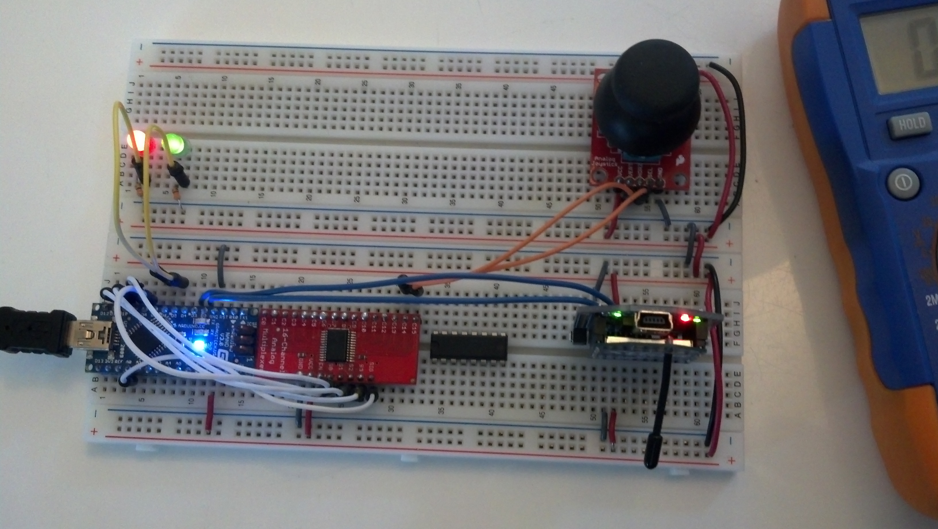
I didn’t mention in in the video, but I moved the mux from the controller, to the vehicle. It allows me to have 22 analog inputs, and the reason I took so long to finally add it was primarily laziness on my part. Aside from the the code is still very similar but close followers will notice that I cleaned up the way the program receives and sends code. It is much much more organized, and much more expandable. Here’s the “new” controller:

Here’s the new program:
|
1 2 3 4 5 6 7 8 9 10 11 12 13 14 15 16 17 18 19 20 21 22 23 24 25 26 27 28 29 30 31 32 33 34 35 36 37 38 39 40 41 42 43 44 45 46 47 48 49 50 51 52 53 54 55 56 57 58 59 60 61 62 63 64 65 66 67 68 69 70 71 72 73 74 75 76 77 78 79 80 81 82 83 84 85 86 87 88 89 90 91 92 93 94 95 96 97 98 99 100 101 102 103 104 105 106 107 108 109 110 111 112 113 114 115 116 117 118 119 120 121 122 123 124 125 126 127 128 129 130 131 132 133 134 135 136 137 138 139 140 141 142 143 144 145 146 147 148 149 150 151 152 153 154 155 156 157 158 159 160 161 162 163 164 165 166 167 168 169 170 171 172 173 174 175 176 177 178 179 180 181 182 183 184 185 186 187 188 189 190 191 192 193 194 195 196 197 198 199 200 201 202 203 204 205 206 207 208 209 210 211 212 213 214 215 216 217 218 219 220 221 222 223 224 225 226 227 228 229 230 231 232 233 234 235 236 237 238 239 240 241 242 243 244 245 246 247 248 249 250 251 252 253 254 255 256 257 258 259 260 261 262 263 264 265 266 267 268 269 270 271 272 273 274 275 276 |
//Serial Handshake declaration #include <string.h> // we'll need this for subString #define MAX_STRING_LEN 100 // like 3 lines above, change as needed. const char EOPmarker = '.'; //This is the end of packet marker char serialbuf[100]; //This gives the incoming serial some room. Change it if you want a longer incoming. //SoftwareSerial declaration #include <SoftwareSerial.h> SoftwareSerial xbee_serial(8, 9); //Mux control pins declarations int s0 = 2; int s1 = 3; int s2 = 4; int s3 = 7; int SIG_pin = 0; //Shift Register Pins declaration int SER_Pin = 10; //pin 14 on the 75HC595 int RCLK_Pin = 11; //pin 12 on the 75HC595 int SRCLK_Pin = 12; //pin 11 on the 75HC595 #define number_of_74hc595s 1 //How many of the shift registers - change this #define numOfRegisterPins number_of_74hc595s * 8 //do not touch boolean registers[numOfRegisterPins]; //Servo declarations #include <Servo.h> Servo left_servo; Servo rght_servo; //Misc Pin declaration //inputs int debug_switch1 = 4; //outputs //these values are for communication, not hardware outputs int out_ref; int out_pot1; int out_pot2; int out_accelerometer_x; int out_accelerometer_y; int out_accelerometer_z; int out_temp1; int fade_LED = 13; int x_LED = 5; int y_LED = 6; //int debug_switch1_LED = 12; //Misc Integer declarations int in_brightness; int in_joystick_x; int in_joystick_y; int brightness = 0; // how bright the LED is int fadeAmount = 51; // how many points to fade the LED by int x_upperTrigger = 600; int x_lowerTrigger = 450; int y_upperTrigger = 600; int y_lowerTrigger = 400; void setup(){ Serial.begin(9600); xbee_serial.begin(9600); //mux setup pinMode(s0, OUTPUT); pinMode(s1, OUTPUT); pinMode(s2, OUTPUT); pinMode(s3, OUTPUT); digitalWrite(s0, LOW); digitalWrite(s1, LOW); digitalWrite(s2, LOW); digitalWrite(s3, LOW); //shift register setup pinMode(SER_Pin, OUTPUT); pinMode(RCLK_Pin, OUTPUT); pinMode(SRCLK_Pin, OUTPUT); clearRegisters(); writeRegisters(); //misc pin declarations pinMode(x_LED, OUTPUT); pinMode(y_LED, OUTPUT); pinMode(fade_LED, OUTPUT); xbee_serial.print("0,0,0."); // this is very important as it starts of the loop because it makes "xbee_serial.avalible() > 0. } void loop(){ if (xbee_serial.available() > 0) { static int bufpos = 0; char inchar = xbee_serial.read(); if (inchar != EOPmarker) { serialbuf[bufpos] = inchar; bufpos++; } else { serialbuf[bufpos] = 0; //restart the buff bufpos = 0; //restart the position of the buff handshake(); setRegisterPin(1, HIGH); writeRegisters(); } } } void handshake(){ //inputs in_brightness = atoi(subStr(serialbuf, "," , 1)); in_joystick_x = atoi(subStr(serialbuf, "," , 2)); in_joystick_y = atoi(subStr(serialbuf, "," , 3)); analogWrite(fade_LED,in_brightness); if (in_joystick_x > x_upperTrigger){ //the below boolean blocks set pins high or low setRegisterPin(4,HIGH); setRegisterPin(5,LOW); analogWrite(x_LED, map(in_joystick_x,x_upperTrigger,1023,0,255)); writeRegisters(); } if (in_joystick_x < x_lowerTrigger){ setRegisterPin(4,LOW); setRegisterPin(5,HIGH); analogWrite(x_LED, map(in_joystick_x,x_upperTrigger,0,0,255)); writeRegisters(); } if (in_joystick_x > x_lowerTrigger && in_joystick_x < x_upperTrigger){ setRegisterPin(4,LOW); setRegisterPin(5,LOW); analogWrite(x_LED,0); writeRegisters(); } // x above y below if (in_joystick_y > y_upperTrigger){ setRegisterPin(2,HIGH); setRegisterPin(3,LOW); analogWrite(y_LED, map(in_joystick_y,y_upperTrigger,1023,0,255)); writeRegisters(); } if (in_joystick_y < y_lowerTrigger){ setRegisterPin(2,LOW); setRegisterPin(3,HIGH); analogWrite(y_LED, map(in_joystick_y,y_upperTrigger,0,0,255)); writeRegisters(); } if (in_joystick_y > y_lowerTrigger && in_joystick_y < y_upperTrigger){ setRegisterPin(2,LOW); setRegisterPin(3,LOW); analogWrite(y_LED,0); writeRegisters(); } //outputs brightness = brightness + fadeAmount; // reverse the direction of the fading at the ends of the fade: if (brightness == 0 || brightness == 255) { fadeAmount = -fadeAmount ; } out_ref = readMux(15); out_pot1 = readMux(0); out_pot2 = readMux(1); out_accelerometer_x = readMux(2); out_accelerometer_y = readMux(3); out_accelerometer_z = readMux(4); out_temp1 = readMux(5); xbee_serial.print(out_ref); xbee_serial.print(","); xbee_serial.print(brightness); xbee_serial.print(","); xbee_serial.print(out_pot1); xbee_serial.print(","); xbee_serial.print(out_pot2); xbee_serial.print(","); xbee_serial.print(out_accelerometer_x); xbee_serial.print(","); xbee_serial.print(out_accelerometer_y); xbee_serial.print(","); xbee_serial.print(out_accelerometer_z); xbee_serial.print(","); xbee_serial.print(out_temp1); xbee_serial.print("."); //EOP marker delay(10); } // for substring char* subStr (char* input_string, char *separator, int segment_number) { char *act, *sub, *ptr; static char copy[MAX_STRING_LEN]; int i; strcpy(copy, input_string); for (i = 1, act = copy; i <= segment_number; i++, act = NULL) { sub = strtok_r(act, separator, &ptr); if (sub == NULL) break; } return sub; } // for mux int readMux(int channel){ int controlPin[] = {s0, s1, s2, s3}; int muxChannel[16][4]={ {0,0,0,0}, //channel 0 {1,0,0,0}, //channel 1 {0,1,0,0}, //channel 2 {1,1,0,0}, //channel 3 {0,0,1,0}, //channel 4 {1,0,1,0}, //channel 5 {0,1,1,0}, //channel 6 {1,1,1,0}, //channel 7 {0,0,0,1}, //channel 8 {1,0,0,1}, //channel 9 {0,1,0,1}, //channel 10 {1,1,0,1}, //channel 11 {0,0,1,1}, //channel 12 {1,0,1,1}, //channel 13 {0,1,1,1}, //channel 14 {1,1,1,1} //channel 15 }; //loop through the 4 sig for(int i = 0; i < 4; i ++){ digitalWrite(controlPin[i], muxChannel[channel][i]); } //read the value at the SIG pin int val = analogRead(SIG_pin); //return the value return val; } // for shift registers void clearRegisters(){ for(int i = numOfRegisterPins - 1; i >= 0; i--){ registers[i] = LOW; } } // for shift registers void writeRegisters(){ digitalWrite(RCLK_Pin, LOW); for(int i = numOfRegisterPins - 1; i >= 0; i--){ digitalWrite(SRCLK_Pin, LOW); int val = registers[i]; digitalWrite(SER_Pin, val); digitalWrite(SRCLK_Pin, HIGH); } digitalWrite(RCLK_Pin, HIGH); } //set an individual pin HIGH or LOW void setRegisterPin(int index, int value){ registers[index] = value; } |
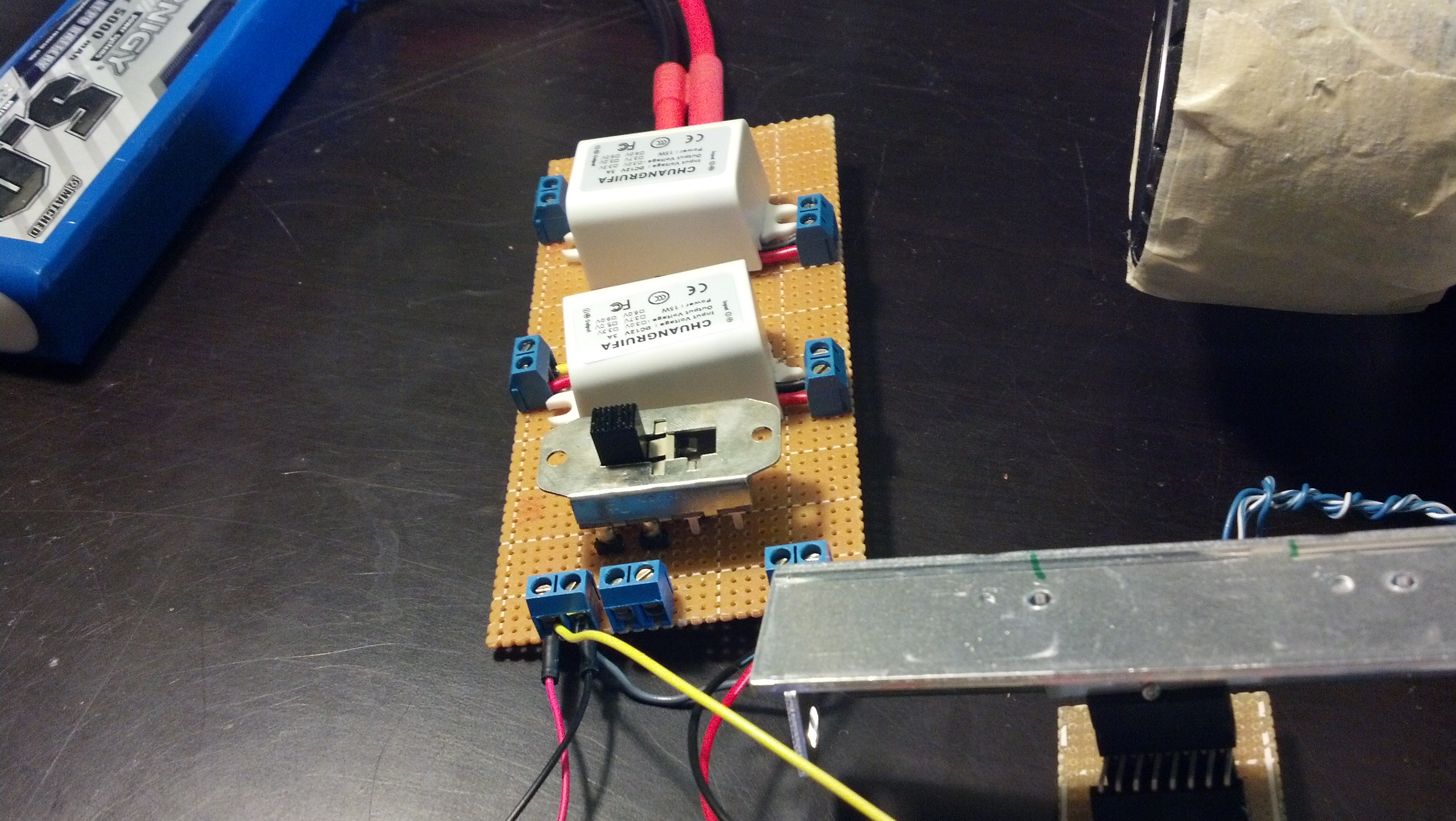
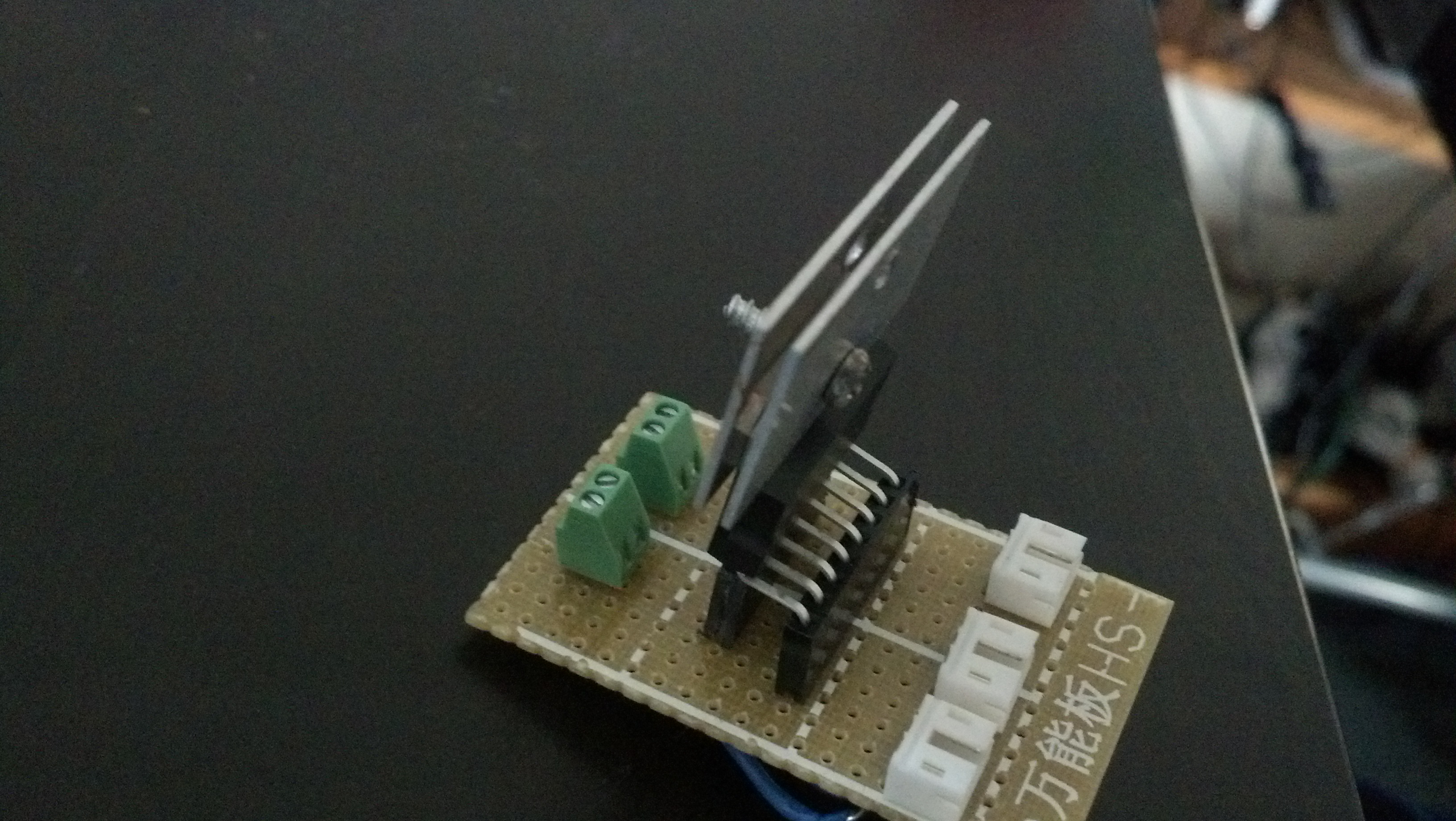
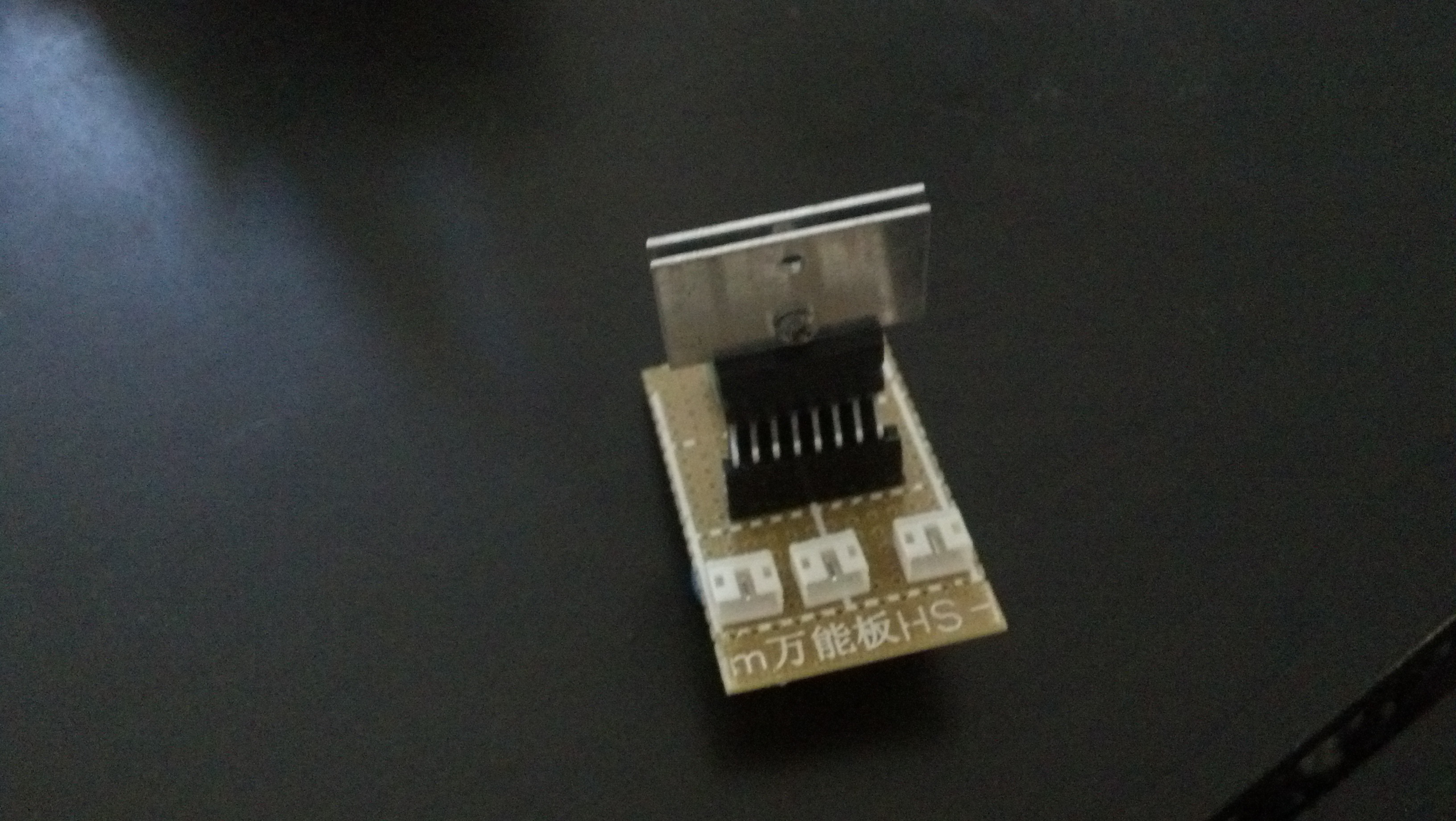
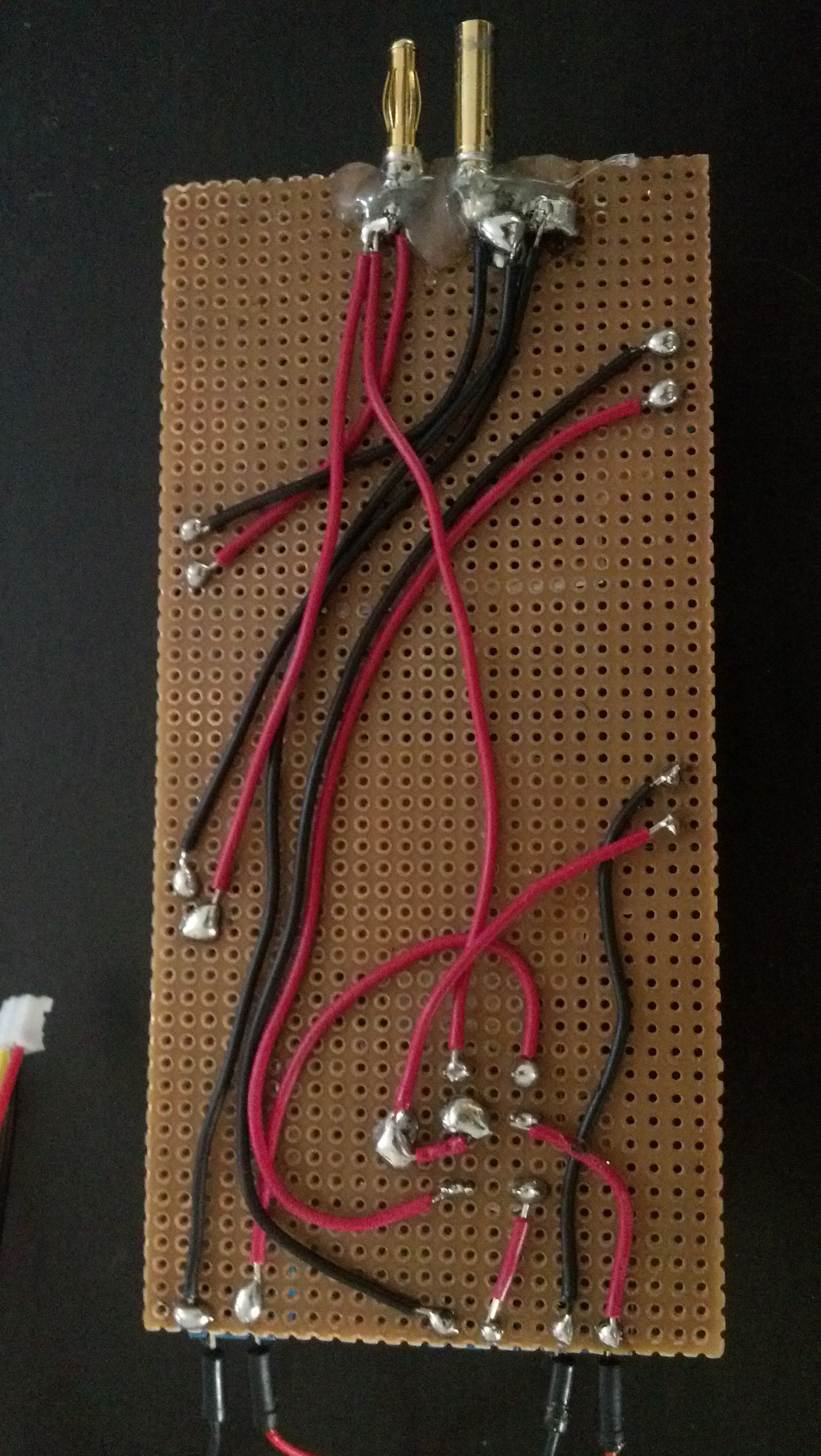
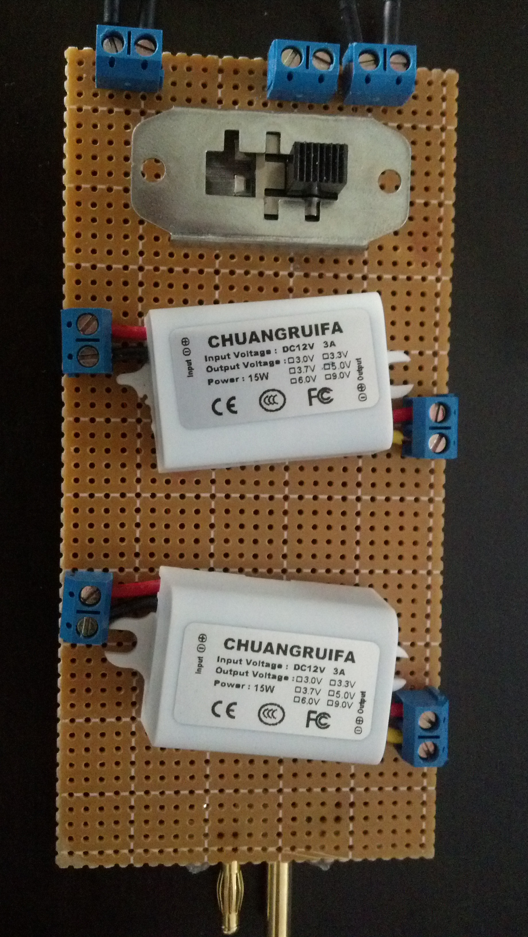
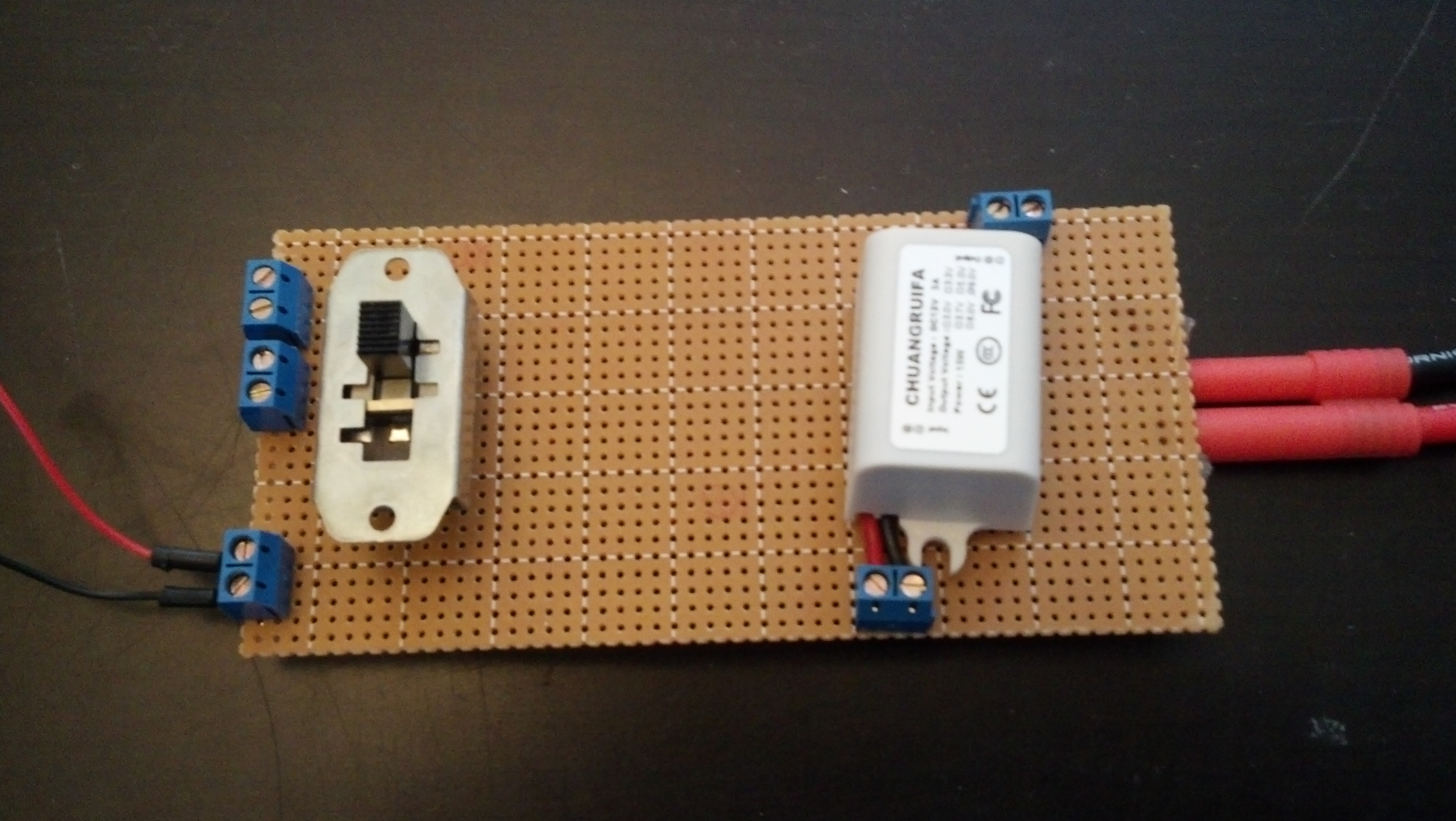
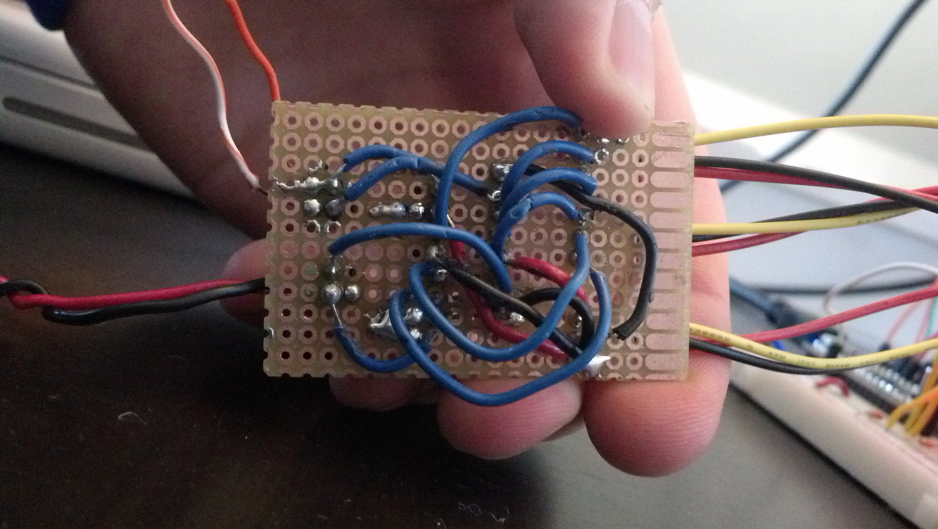
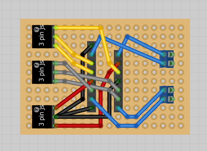
Like I promised in the video, here are a few more properly focused pictures: