Turns out it’s not that hard at all! Here’s a video of the whole thing working:
This basically works around concepts I first explained here. It’s still really cool though! SPI is really fast and really easy to use, perfect for a novice like me.
Here are the physical representations and schematics of the setup seen on my desk:
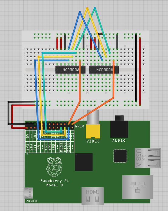
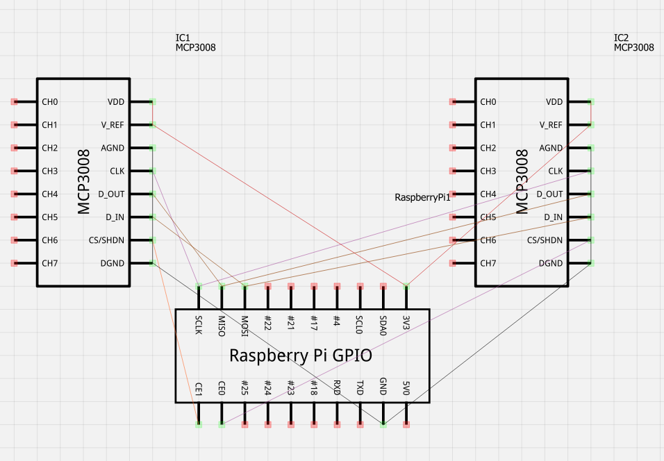
Images generated by fritzing.
Here’s the code that makes it all work!
|
1 2 3 4 5 6 7 8 9 10 11 12 13 14 15 16 17 18 19 20 21 22 23 24 25 26 27 28 29 30 |
#first ADC setup on SPI port 0 import spidev spi_0 = spidev.SpiDev() spi_0.open(0, 0) #this fucntion can be used to find out the ADC value on ADC 0 def readadc_0(adcnum_0): if adcnum_0 > 7 or adcnum_0 < 0: return -1 r_0 = spi_0.xfer2([1, 8 + adcnum_0 << 4, 0]) adcout_0 = ((r_0[1] & 3) << 8) + r_0[2] return adcout_0 #first ADC setup on SPI port 1 import spidev spi_1 = spidev.SpiDev() spi_1.open(0, 1) #this fucntion can be used to find out the ADC value on ADC 1 def readadc_1(adcnum_1): if adcnum_1 > 7 or adcnum_1 < 0: return -1 r_1 = spi_1.xfer2([1, 8 + adcnum_1 << 4, 0]) adcout_1 = ((r_1[1] & 3) << 8) + r_1[2] return adcout_1 while 1: for x in range (0, 8): print 'Port ' + str(x) + ' | ' + 'adc_0: ' + str(readadc_0(x)).zfill(4) + ' | ' + 'adc_1: ' + str(readadc_1(x)).zfill(4) print '----------------------------------' |
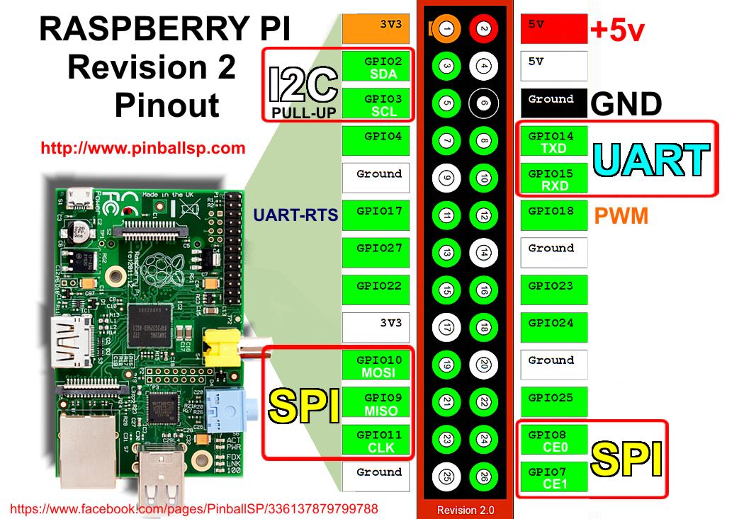
Here is some further reading:
http://www.megaleecher.net/sites/default/files/images/raspberry-pi-rev2-gpio-pinout.jpg
http://hertaville.com/2013/07/24/interfacing-an-spi-adc-mcp3008-chip-to-the-raspberry-pi-using-c/
http://tightdev.net/SpiDev_Doc.pdf
Thanks for reading!