
This project got featured on the official arduino blog as well as hackaday! Thanks to everyone that shared!
I work with addressable LEDs a lot. For all that they’re great for, they’re kind of hard to debug when you have a lot of them connected up at once. This is especially apparent when you have many small single modules in hard to reach spaces.
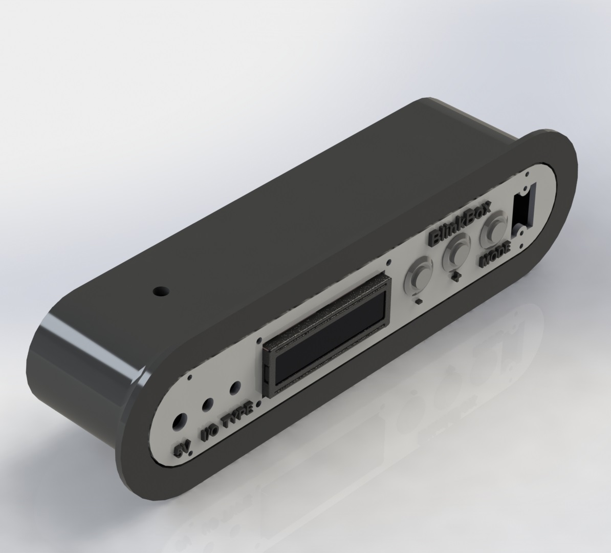
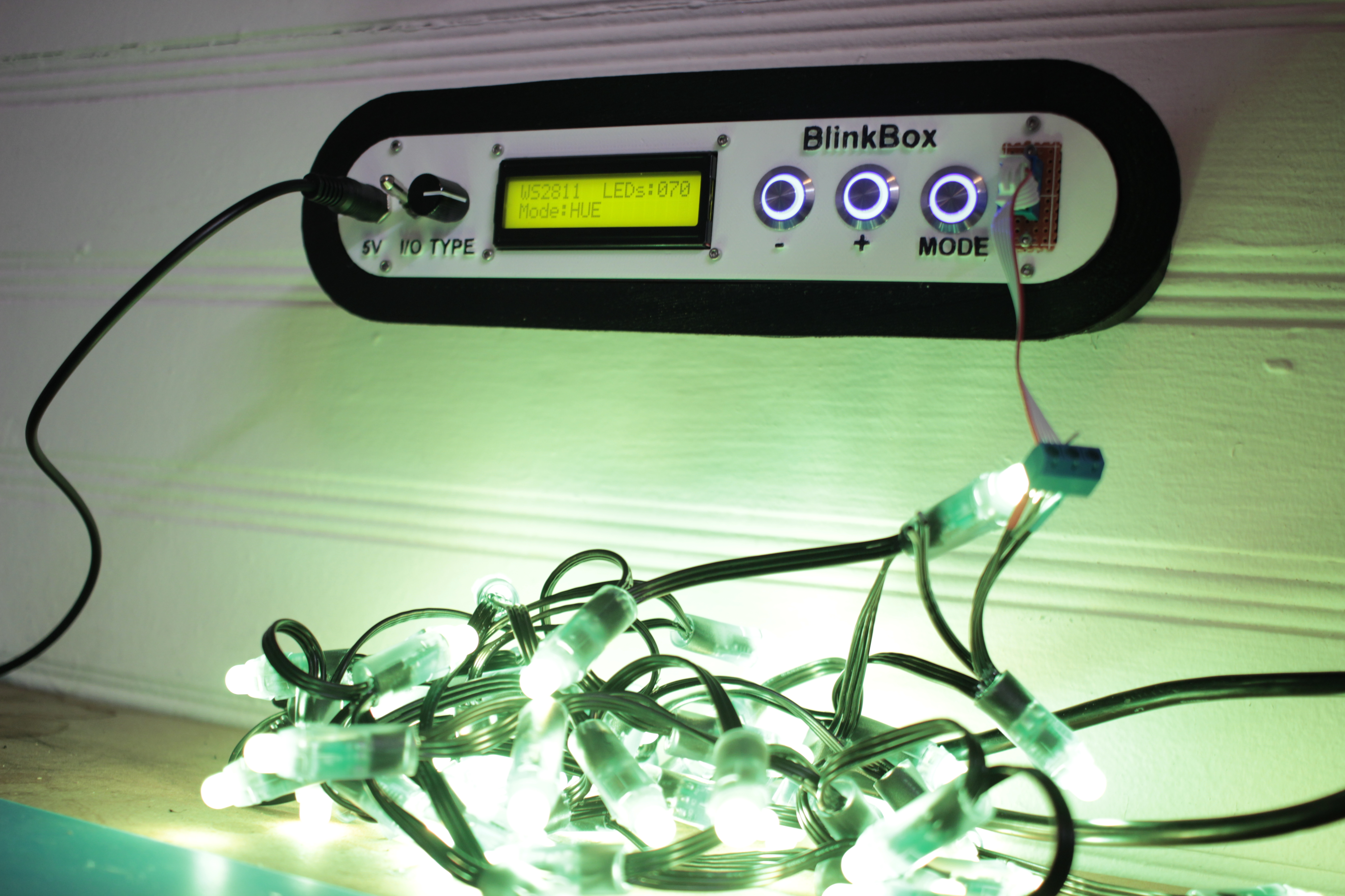
Here’s my solution:
This lets me set the color and number of LEDs in a strip, and then displays a color pattern. This way I can tell if an LED has become disconnected in a strip, or if a channel inside a particular has died.
Features
- Select LED type with the type switch, 4 positions
- Can test up to 400 LEDs at a time, if you can find a worthy power supply
- 3 Test modes
- RGB – 1 second red, 1 second green, 1 second blue
- HUE – Lock strip at
HSV (x, 255, 255)and x loops from 0-255 - WHTE – Set the strip to
RGB(255, 255, 255)
- Count and Mode are saved into eeprom, so you don’t have to keep resetting the strip if it powers off
- Wall mount fittings
Design Explanation
All of the raw code solidworks, and KiCAD have been posted on my github. You can look at the 3D models on thingiverse as well.
Mechanical
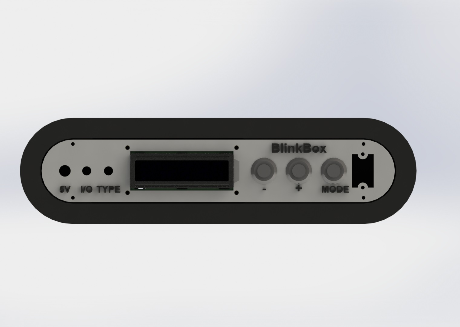
Here are a couple of quick renders of the assembly design:
 The screw mount behind the pushbuttons is extended to be able to support the pressure without flexing:
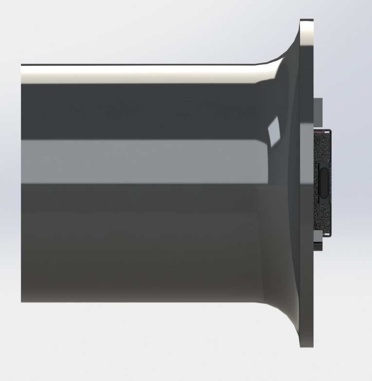
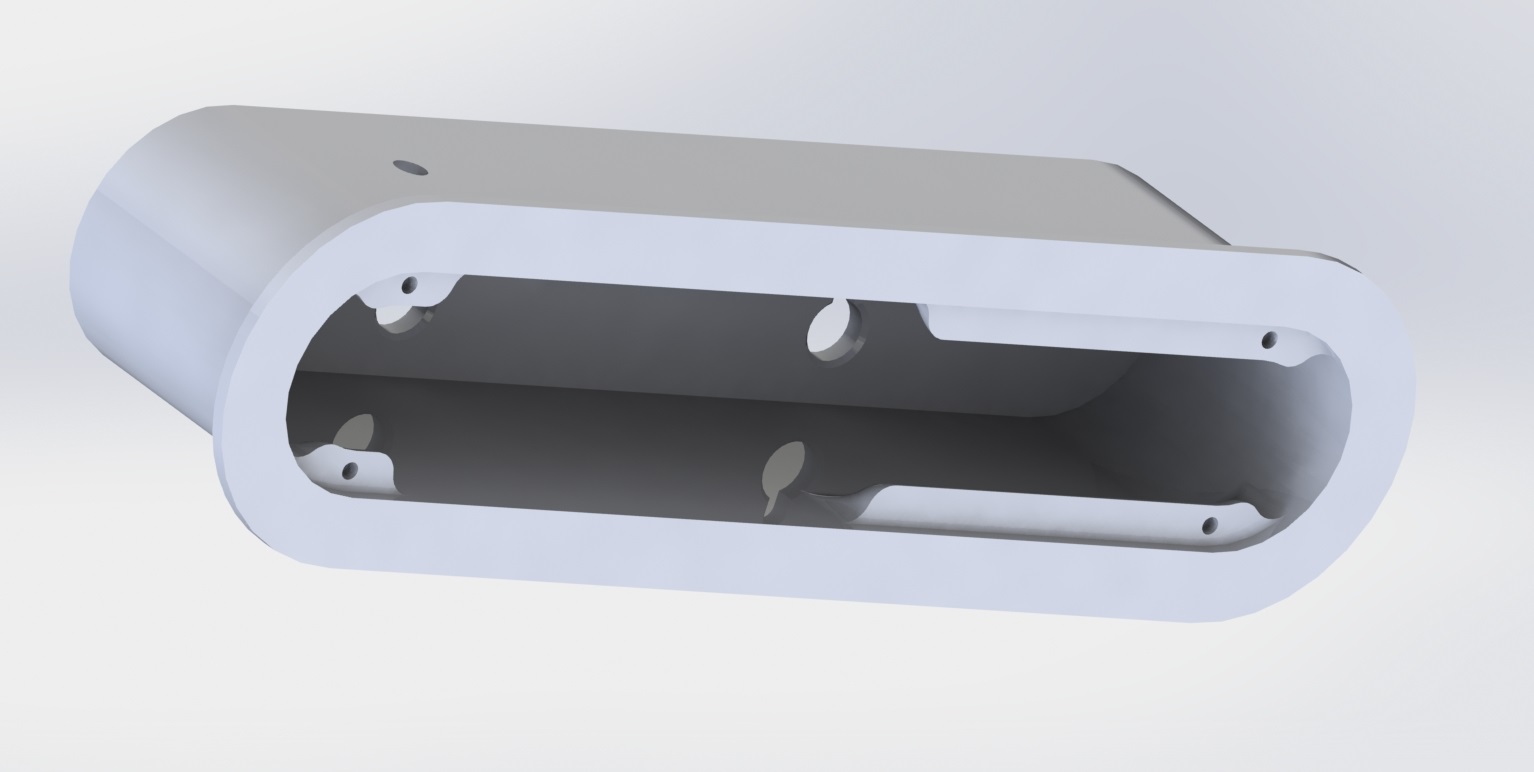 I added a ridge so you can grab onto something as you interact with the switches / buttons.
Electronics
Here’s the circuit:
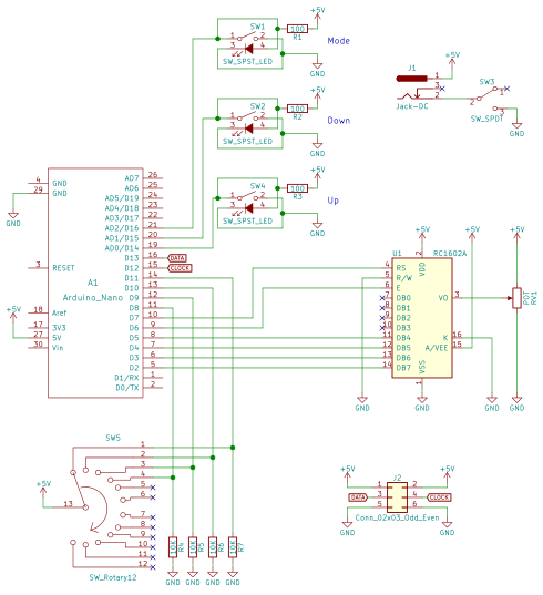
There really isn’t a lot going on here, the parts are probably the coolest part of the project. The 5V jack is a 6mm DC barrel jack, the pushbuttons are illuminated 16mm pushbuttons from adafruit, the on/off switch is a locking toggle switch, and the 4 position rotary switch can be found here.
I wired up the circuit on a spare piece of perfboard.
Software
My code is available on my github.
The LED driving part of the code is based on FastLED, a beautiful library for driving these types of addressable LEDs.
The rest of the code is mostly just a hardware UI problem, and isn’t all that interesting. LED count “ramps” as you hold the button down. The longer you hold the button, the faster the
Wrap up
That’s pretty much it! I’ve already gotten some use out of this tool and have found great satisfaction in taking the time to make it look nice as it will be a permanent addition to my lab.
I’ll post any updates I make to this project as edits to the top of this post.
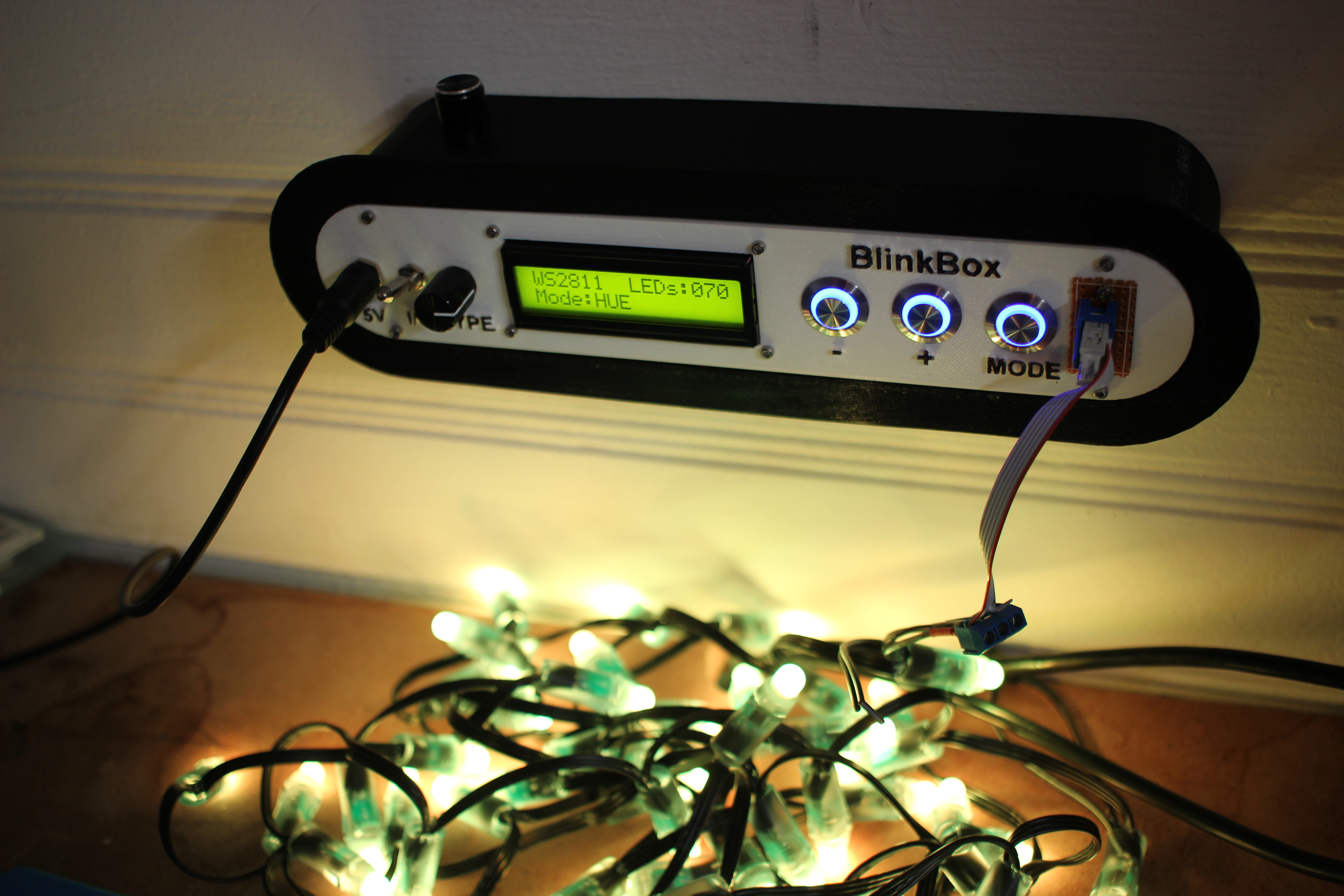
Thanks for reading, and here are a few more photos:
I’m not great at electronics, but R1-R3, though probably fine for their LED current limiting function, are doubling as pull-up resistors for the switches. At 100 ohms at 5v, they will pull 50ma each. Probably not terrible for something on a large power supply, but that also equals 1/4 watt dissipation, which is probably right at the rating for most resistors used by hobbyists.
Increasing the values of R1-R3 might not affect the LED brightness greatly, and would make the components run cooler, last longer, and be safer for the circuit. If it would make the LEDs too dim for your taste, perhaps adding a second, high-value resistor in each place to handle the pull-up function would be an option.
As I mentioned, I’m not an expert. Perhaps the Arduino is further limiting the current through internal pullups, but I have never trusted internal pullups if I could avoid it.