Ever wanted to measure the frequency of a square wave using an Arduino? There are a couple of good solutions out of there to do this, but not all of them had the capacity to do multiple inputs. I couldn’t find this quickly so here is my solution.
Here’s the link to the code if you want to skip ahead. The code uses interrupts and doesn’t use any kind of delaying so it’s good for giant state-machine applications. My application for this is measuring signals from 10Hz-100Hz in which this can measure within 1% error. The absolute limits of the code are 1Hz-50KHz.
This project is on GitHub if you want to send a pull request to make improvements.
Setup
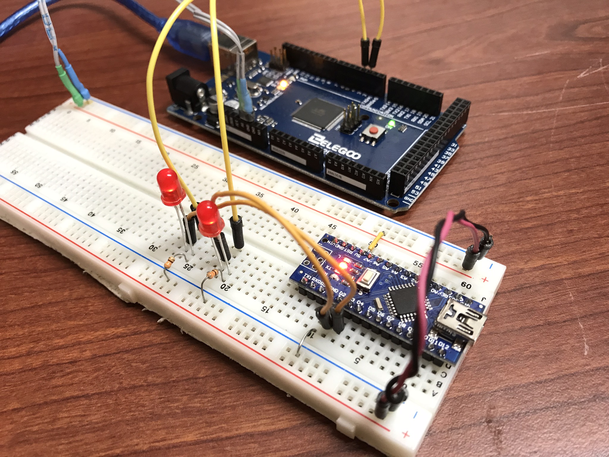
For testing, I wrote a simple function generator and uploaded it to a separate arduino. It outputs a pulse train with periods of 10ms (100Hz) and 5ms (200Hz) on pins 2 and 3. I attached LEDs and their resistors for debugging.
Pins 2 and 3 on the function generator to pins 2 and 3 on the frequency counter.
The code for this simple function generator is here:
/*
 * 3/29/2018 - Devon Bray - https://www.esologic.commultiple-frequency-counter-arduino/
 */


int pin_100Hz = 2;
int pin_200Hz = 3;

unsigned long previous_time_100Hz;
unsigned long previous_time_200Hz;

void setup() {
  pinMode(pin_100Hz, OUTPUT);
  pinMode(pin_200Hz, OUTPUT);
}

void loop() {

  unsigned long current_time = millis();

  if ( (current_time - previous_time_200Hz) >= 5) {
    digitalWrite(pin_200Hz, HIGH);
    delayMicroseconds(1000);
    digitalWrite(pin_200Hz, LOW);
    previous_time_200Hz = current_time;
  }

  if ( (current_time - previous_time_100Hz) >= 10) {
    digitalWrite(pin_100Hz, HIGH);
    delayMicroseconds(1000);
    digitalWrite(pin_100Hz, LOW);
    previous_time_100Hz = current_time;
  }

}
Frequency Counter
This code will work fine in a stateless application, because there are no delay statements (which some other frequency counters I’ve seen online use). It’s a little bit complicated, send me a pull request if you can refactor it to be cleaner.
Here’s the sketch:
/*
 * 3/29/2018 - Devon Bray - https://www.esologic.commultiple-frequency-counter-arduino/
 *
 * I've written most of the important notes as comments in the source, but a couple more details:
 *
 * - The important data is stored in `period_averages_ms` and `frequency_averages_hz`. You address them using the indices defined at the top of the file. These arrays get updated each time `compute_counts()` is called. Keep it `compute_counts()` somewhere in the main() loop.
 *
 * - You could easily add more frequencies, you just have to `NUMSIGS`, make a specific ISR, and another `attachInterrupt` line in setup()
 *
 * - It uses [interrupts](https://playground.arduino.cc/Code/Interrupts) which might not be right for your proejct, but normally shouldn't get in the way of too much stuff.
 *
 * - If the ISR hasn't seen a new edge in 1000000us, both `period_averages_ms[p_index]` and `frequency_averages_hz[p_index]` will be set to zero!
 * - This means that slowest frequency that this code can detect is 1hz!
 *
 */

int freq_pin_1 = 2; // the pin connected to the first signal, must be an interrupt pin! See the arduino docs
int freq_pin_2 = 3; // the pin connected to the second signal, must be an interrupt pin! See the arduino docs

#define BUFFSIZE 100 // a rolling average of the frequency/period is computed, and this is the size of that buffer

#define NUMSIGS 2
#define FREQ1INDEX 0
#define FREQ2INDEX 1

volatile int period_buffer_indices[NUMSIGS] = { 0 }; // the location of the index for adding to the rolling buffer average
volatile unsigned long period_buffers[NUMSIGS][BUFFSIZE] = { 0 }; // the buffers
volatile unsigned long previous_edge_times_us[NUMSIGS] = { 0 }; // the time that the previous edge came in in microseconds
volatile float period_averages_ms[NUMSIGS] = { 0 }; // the period time of a given signal in milliseconds
volatile float frequency_averages_hz[NUMSIGS] = { 0 }; // the frequency of a given signal in hertz
volatile bool period_buffer_locked[NUMSIGS] = { false }; // spin locks for the different buffers

void setup() {

  Serial.begin(9600);

  // the pins must be mapped to their ISRs

  pinMode(freq_pin_1, INPUT_PULLUP);
  attachInterrupt(digitalPinToInterrupt(freq_pin_1), new_freq1_edge, RISING); // you could change this mode to whatever you were looking for, FALLING, CHANGE etc.

  pinMode(freq_pin_2, INPUT_PULLUP);
  attachInterrupt(digitalPinToInterrupt(freq_pin_2), new_freq2_edge, RISING);
}

void loop() {

  compute_counts();

  Serial.print("Pin 1: ");
  Serial.print(period_averages_ms[FREQ1INDEX]);
  Serial.print("ms, ");
  Serial.print(frequency_averages_hz[FREQ1INDEX]);
  Serial.print(" hz");

  Serial.print(" - Pin 2: ");
  Serial.print(period_averages_ms[FREQ2INDEX]);
  Serial.print("ms, ");
  Serial.print(frequency_averages_hz[FREQ2INDEX]);
  Serial.print(" hz");
  Serial.println("");
}

void compute_counts() {

  // computes the average of the buffer for a given signal. Must be called before using the period_averages_ms or frequency_averages_hz buffers.

  for (int p_index = 0; p_index < NUMSIGS; p_index++) {

    float buffer_sum = 0;

    while (period_buffer_locked[p_index]) {}; // wait around for the ISR to finish

    period_buffer_locked[p_index] = true; // ISR won't add new data to `period_buffers`
    if ((micros() - previous_edge_times_us[p_index]) < 1000000) {
      for (int j = 0; j < BUFFSIZE; j++) {
        buffer_sum += period_buffers[p_index][j];
      }
    }
    period_buffer_locked[p_index] = false; // ISR will now add new data to `period_buffers`

    if (buffer_sum > 0){
      period_averages_ms[p_index] = ((buffer_sum / (float)BUFFSIZE)) / 1000;
      frequency_averages_hz[p_index] = (1 / period_averages_ms[p_index]) * 1000;
    }
    else {
      period_averages_ms[p_index] = 0;
      frequency_averages_hz[p_index] = 0;
    }

  }
}

void new_edge(int period_index) {

  unsigned long current = micros();

  if (period_buffer_locked[period_index] == false) { // if compute_counts is using the buffer, skip adding to it because that process isn't atomic

    period_buffer_locked[period_index] = true;

    period_buffers[period_index][period_buffer_indices[period_index]] = current - previous_edge_times_us[period_index];

    period_buffer_locked[period_index] = false;

    period_buffer_indices[period_index]++;
    if (period_buffer_indices[period_index] >= BUFFSIZE) {
      period_buffer_indices[period_index] = 0;
    }
  }

  previous_edge_times_us[period_index] = current; // but make sure the new time is set because this operation is atomic

}

void new_freq1_edge() {
  new_edge(FREQ1INDEX);
}

void new_freq2_edge() {
  new_edge(FREQ2INDEX);
}
I’ve written most of the important notes as comments in the source, but a couple more details:
- The important data is stored in `period_averages_ms` and `frequency_averages_hz`. You address them using the indices defined at the top of the file. Make sure you call `compute_counts()` before using this data. Keep it somewhere in
main().
- You could easily add more frequencies, you just have to `NUMSIGS`, make a specific ISR, and another `attachInterrupt` line in
setup()
- It uses interrupts which might not be right for your proejct, but normally shouldn’t get in the way of too much stuff.
- If the ISR hasn’t seen a new edge in 1000000us, both
period_averages_ms[p_index] and frequency_averages_hz[p_index] will be set to zero! This means that slowest frequency that this code can detect is 1Hz!
If you have any questions on how to add more signals, leave a comment!
Results
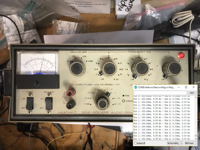
Here’s the output in the serial monitor attached to my function generator from earlier:
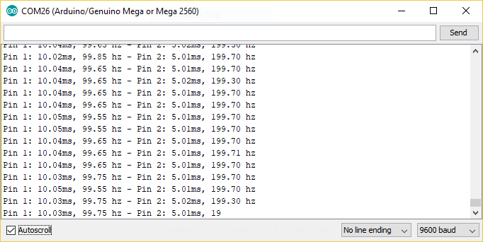
That’s like less than 1% error! Pretty good!
I also tested the code with a real function generator. Things worked really well until around 50KHz, so I would say that this code can’t be trusted past 50KHz.
10 Hz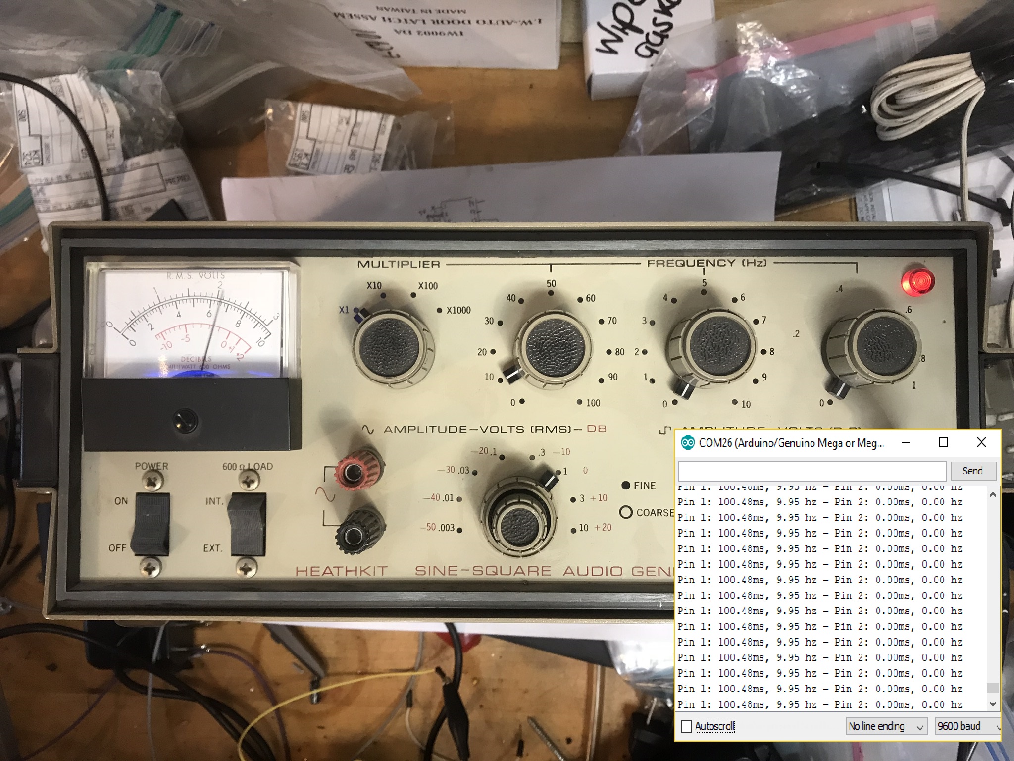
50 KHz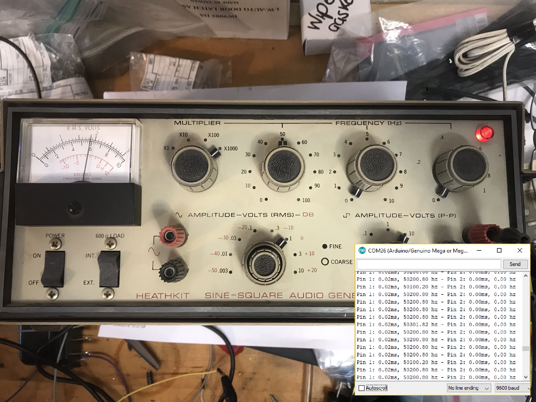
Thanks for reading!