I’m taking a “break” from my drone while I save some money to buy more tricopter parts, and since the weather’s getting nicer and nicer I’ve decided to start working on my PiPlanter again.
As a refresher, the PiPlanter is a Raspberry Pi powered garden. The goal is for it to just be able to be plugged in and add water to a water source and have the Pi monitor temp and moisture levels to be able to add more water as needed.
I’ve shown that is relatively easy to go from analog sensors to good looking tables and graphs using the raspberry pi, the problem that I ran into however was timing.
It became harder and harder to use the time.sleep function in python to handle long periods of time. When you are dealing with things like plants, you don’t need to water it very often, but for data’s sake, you should be polling the sensors a lot.
I’ve landed on the use of APScheduler in python, and here’s my source code:
[py]
#Timing setup
from datetime import datetime
from apscheduler.scheduler import Scheduler
import time
import logging #if you start getting logging errors, uncomment these two lines
logging.basicConfig()
#GPIO setup
import RPi.GPIO as GPIO
GPIO.setmode(GPIO.BOARD)
GPIO.cleanup()
pin = 26 #pin for the adc
GPIO.setup(pin, GPIO.OUT)
led1 = 11 #pin for the short indicator led
GPIO.setup(led1, GPIO.OUT)
led2 = 13 #pin for other long indicator led
GPIO.setup(led2, GPIO.OUT)
#the adc’s SPI setup
import spidev
spi = spidev.SpiDev()
spi.open(0, 0)
going = True
#fuction that can read the adc
def readadc(adcnum):
# read SPI data from MCP3008 chip, 8 possible adc’s (0 thru 7)
if adcnum > 7 or adcnum < 0:
return -1
r = spi.xfer2([1, 8 + adcnum << 4, 0])
adcout = ((r[1] & 3) << 8) + r[2]
return adcout
def rapidSample():
sampleTemp1 = (((readadc(0)*3.3)/1024)/(10.0/1000)) #this translates the analog voltage to temperature in def F
sampleLght1 = readadc(1)
samplePot1 = readadc(2)
GPIO.output(led1, True) #turns the led on
time.sleep(.1) #sleeps a little bit so you can see the LED on
print "Job 1", datetime.now(),"LDR:",sampleLght1 ,"Pot:",samplePot1,"Temp:",sampleTemp1 #prints the debug info
time.sleep(.1)
GPIO.output(led1, False) #turns the led off
def slowSample():
print "Job 2" , datetime.now()
GPIO.output(led2, True) #turns the led on
time.sleep(5)
GPIO.output(led2, False) #turns the led on
if __name__ == ‘__main__’:
#the following 3 lines start up the interval job and keep it going
scheduler = Scheduler(standalone=True)
scheduler.add_interval_job(rapidSample, seconds=1)
scheduler.add_interval_job(slowSample, minutes=1)
scheduler.start()
[/py]
This produces a loop that flashed a green led on and of for .1 seconds at a time per second, and then every minute, turns on a speaker and a red led for 5 seconds then turns it off. There are some images of what goes on below.
Here is a picture of the the print dialog in python:
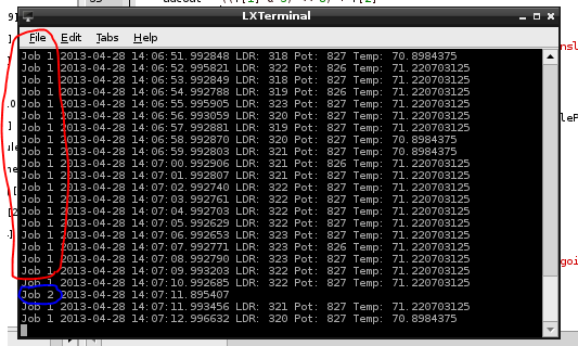
You can see that the first job (green led) posts the values from the analog sensors every second
The second job (red led) just posts the time. But the function is expandable to do anything at any time.
Here are pictures of the board and the circuit in action:
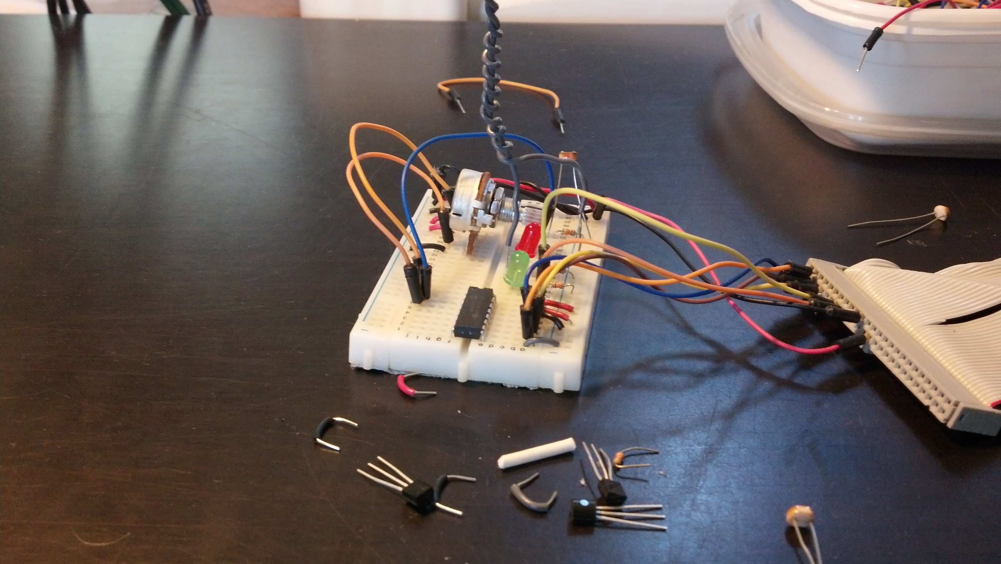
Both LED’s off
The Green LED on, the red circled process in the printout
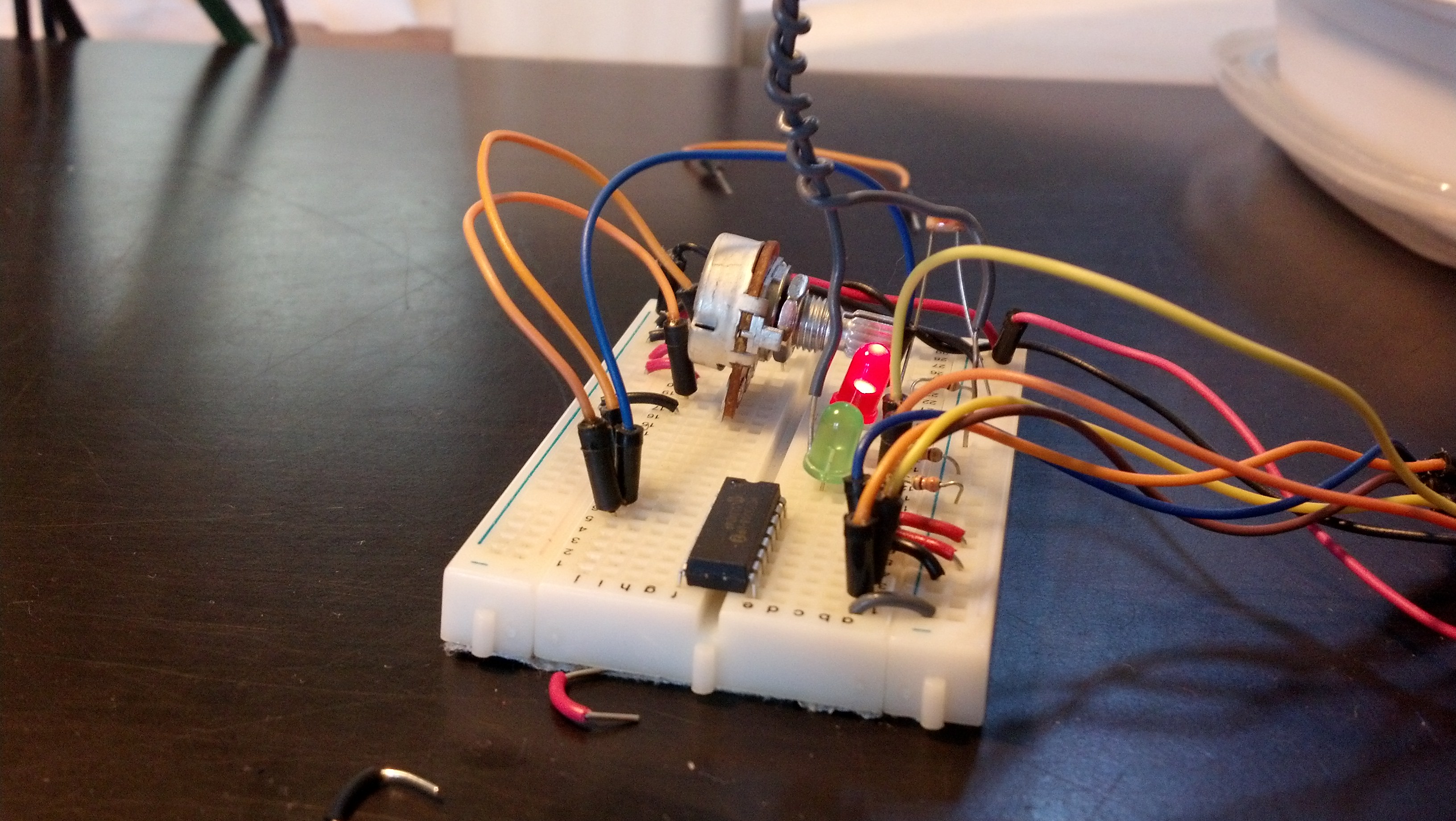
Here are both on
The next step is adding the mySQL in as seen in some other posts.